Reference Thermal Solutions
R
Intel
®
E7500/E7505 Chipset MCH Thermal Design Guide 27
6.3.3 Mechanical Interface Material
Intel recommends the use of a mechanical interface material to avoid cracking of the exposed die
under loading. The interface material reduces mechanical loads experienced by the die. The
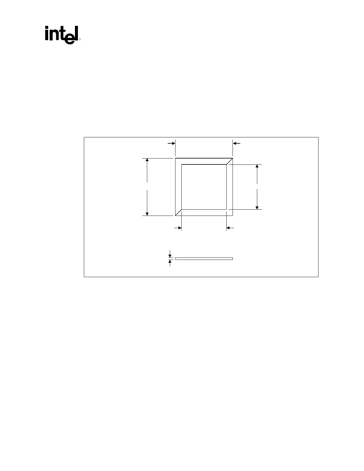
reference thermal solution uses a picture frame gasket of 0.813 mm (0.032 in.) thick Poron* foam.
The foam gasket is a two-piece design with diagonal cuts at two corners as shown in Figure 14. A
one-piece gasket design may be used instead without any impact to mechanical performance.
Figure 14. Heatsink Mechanical Gasket, Optional Two-Piece
42.34 mm (1.667 in.)
33.20 mm (1.307 in.)
33.20 mm (1.307 in.)
42.34 mm (1.667 in.)
0.81 mm (0.032 in.)
Heatsink_Gasket
NOTE: Not to scale.
6.3.4 Thermal Interface Material
A thermal interface material provides improved conductivity between the die and heatsink. The
reference thermal solution uses Chomerics* T-710, 0.127 mm (0.005 in.) thick,
25.4 mm x 25.4 mm (1.0 in. x 1.0 in.) square.
6.3.5 Heatsink Clip
The reference solution uses a wire clip with hooked ends. The hooks attach to wire anchors to
fasten the clip to the board. See Figure 18 in Appendix B for a mechanical drawing of the clip.