Reference Thermal Solutions
R
28 Intel
®
E7500/E7505 Chipset MCH Thermal Design Guide
6.3.6 Clip Retention Anchors
For E7500/E7505 chipset-based platforms that have very limited board space, a clip retention
anchor has been developed to minimize the impact of clip retention on the board. It is based on a
standard three-pin jumper and is soldered to the board like any common through-hole header. A
new anchor design is available with 45° bent leads to increase the anchor attach reliability over
time. See Appendix A for the part number and supplier information.
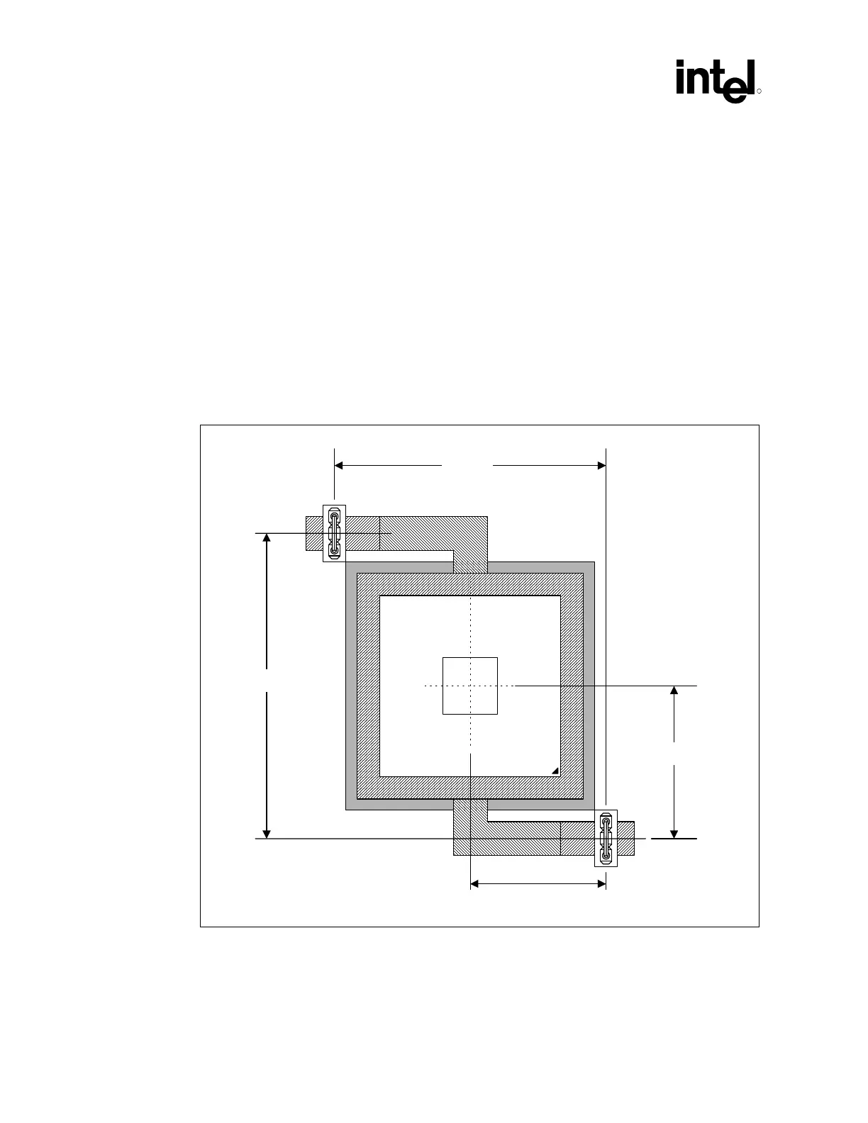
6.3.7 Board Level Component Keep-out Dimensions
The locations of hole patterns and keep-out zones for the reference thermal solution are shown in
Figure 15 and Figure 16.
Figure 15. Heatsink Retention Mechanism Layout
850_Anchor_Lay
2.218
2.398
2x 1.199
MCH
2x 1.109
NOTES:
1. Dimensions are in inches.
2. Not to scale.