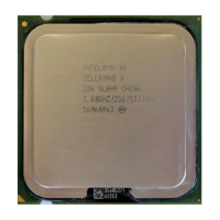
Do you have a question about the Intel EM64T - Celeron D 336 Boxed Ena and is the answer not in the manual?
Defines the objectives and scope of the document regarding thermal management for the processor.
Explains why maintaining component temperatures within range is crucial for performance and longevity.
Lists the specific Pentium 4 processors and related documents covered by this guide.
Provides definitions for key terms used throughout the document.
Details the mechanical specifications and considerations for the processor package and its interaction.
Describes the 775-land LGA package, socket, and integrated heat spreader (IHS).
Covers the mechanisms for attaching a heatsink to the processor package and motherboard.
Specifies the static preload required for the heatsink attachment mechanism.
Introduces new thermal specification parameters: Thermal Profile and TCONTROL.
Defines processor case temperature (TC) and its measurement location on the IHS.
Explains the Thermal Profile as a function of case temperature and power dissipation.
Details TCONTROL as a parameter for controlling fan speed and reducing acoustic noise.
Discusses key factors influencing heatsink performance and design choices.
Explains the role and application of TIM for heat conduction between IHS and heatsink.
Discusses chassis capabilities and methods to improve system thermal performance.
Introduces thermal characterization parameter (Psi) for evaluating thermal solution performance.
Recommends using a Thermal Test Vehicle (TTV) for assessing heatsink performance.
Provides guidelines for accurately measuring local ambient temperature (TA) for testing.
Offers detailed guidelines for accurately measuring processor case temperature (TC) using thermocouples.
Details the integrated Thermal Monitor feature and its components.
Describes the PROCHOT# signal for thermal protection and its bi-directional capability.
Explains the function of the Thermal Control Circuit (TCC) in reducing processor temperature.
Discusses requirements for enabling Thermal Monitor and system design considerations.
Describes the on-die thermal diode and its use for fan speed control.
Explains the THERMTRIP# signal for catastrophic cooling failure shutdown.
Outlines the criteria for validating the Intel reference thermal design.
Specifies the target thermal performance (Psi) for the heatsink for different processor families.
Details acoustic performance requirements for the fan heatsink assembly.
Outlines tests for ensuring the thermal solution's reliability under environmental stress.
Lists safety standards and approvals required for heatsink components.
Describes the Intel RCBFH-3 reference heatsink solution.
Introduces the mechanism used for attaching the heatsink.
Explains the strategy to minimize board deflection during shock for socket protection.
Discusses implementing quieter system designs using TCONTROL and on-die thermal diode.
Covers selecting or designing a thermal solution that meets thermal profiles.
Emphasizes meeting TC-MAX limits at TDP with full fan speed.
Outlines key control settings like TLOW, TCONTROL, and minimum fan speed.
Covers determining the minimum PWM duty cycle for fan speed control.
Details how thermal profile and TCONTROL interact for fan speed management.
Discusses heatsink clip load for mechanical performance and thermal interface.
Defines motherboard deflection measurement for preload assessment.
Specifies the deflection limits for ATX/µATX form factors.
Describes a procedure for measuring heatsink/clip/fastener load.
Details the preparation steps for heatsink clip load testing.
Lists the typical test equipment required for heatsink clip load measurement.
Describes measuring preload at room temperature before environmental stress.
Discusses managing bond line thickness for optimal thermal performance.
Explains factors affecting interface material performance: thermal resistance and wetting.
Defines a reference procedure for attaching thermocouples to the IHS for TC measurement.
Lists recommended equipment for thermocouple attachment and measurement.
Emphasizes the importance of calibrating measurement equipment and controls.
Details the steps for attaching a thermocouple to the IHS.
Provides guidance on managing thermocouple wires to prevent damage.
Details requirements for board-level PWM and fan speed control functionality.
Discusses thermal considerations specific to BTX systems and sensor placement.
Lists the mechanical drawings available in the appendix.
Provides contact information for Intel enabled vendors for thermal solutions.
| Model | Celeron D 336 |
|---|---|
| Architecture | NetBurst |
| Cores | 1 |
| Threads | 1 |
| Base Clock Speed | 2.8 GHz |
| L2 Cache | 256 KB |
| TDP | 84 W |
| Socket | LGA 775 |
| FSB | 533 MHz |
| Lithography | 90 nm |
| Package Type | Boxed |
| Brand | Intel |
| Series | Celeron D |


 Loading...