Case Temperature Reference Metrology
R
Thermal/Mechanical Design Guide 83
Figure 35. Using 3D Micromanipulator to Secure Bead Location
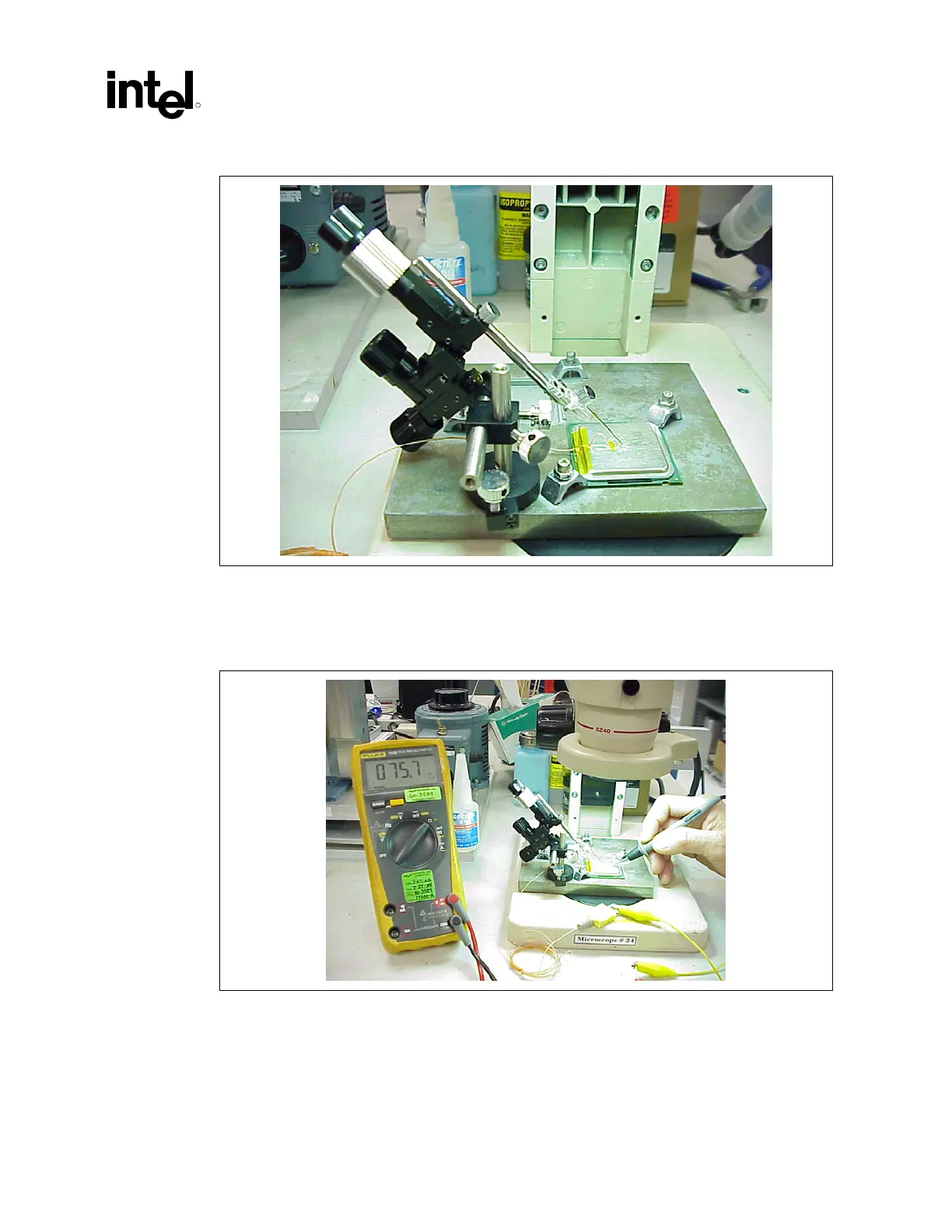
11. Measure resistance from thermocouple end wires (hold both wires to a DMM probe) to the
IHS surface. This should be the same value as measured during the thermocouple
conditioning see Section
D.6.1, step 2 and Figure 36.
Figure 36. Measuring Resistance between Thermocouple and IHS
12. Place a small amount of Loctite 498 adhesive in the groove where the bead is installed. Using
a fine point device, spread the adhesive in the groove around the needle, the thermocouple
bead and the thermocouple wires already installed in the groove during step 5 above. Be
careful not to move the thermocouple bead during this step (
Figure 37).
 Loading...

