Mechanical Drawings
R
Thermal/Mechanical Design Guide 93
Appendix G Mechanical Drawings
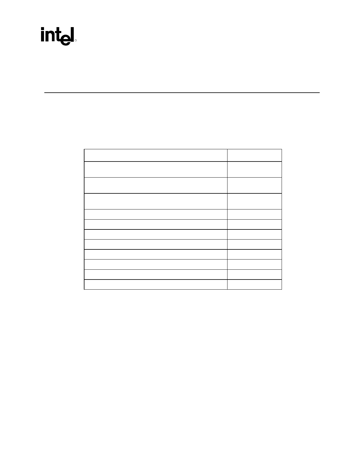
The following table lists the mechanical drawings included in this appendix. These drawings refer
to the reference thermal mechanical enabling components for the Pentium 4 processor in the 775–
land LGA package.
Note: Intel reserves the right to make changes and modifications to the design as necessary.
Drawing Description Page Number
ATX/µATX Motherboard Keep-out Footprint Definition and
Height Restrictions for Enabling Components – Sheet 1
94
ATX/µATX Motherboard Keep-out Footprint Definition and
Height Restrictions for Enabling Components – Sheet 2
95
ATX/µATX Motherboard Keep-out Footprint Definition and
Height Restrictions for Enabling Components – Sheet 3
96
Reference Clip Drawings – Sheet 1 97
Reference Clip Drawings – Sheet 2 98
Reference Fastener – Sheet 1 99
Reference Fastener – Sheet 2 100
Reference Fastener – Sheet 3 101
Reference Fastener – Sheet 4 102
Clip/Heatsink Assembly 103
Intel(R) RCBFH-3 Reference Solution Assembly 104
 Loading...

