GD82559ER — Networking Silicon
70
Datasheet
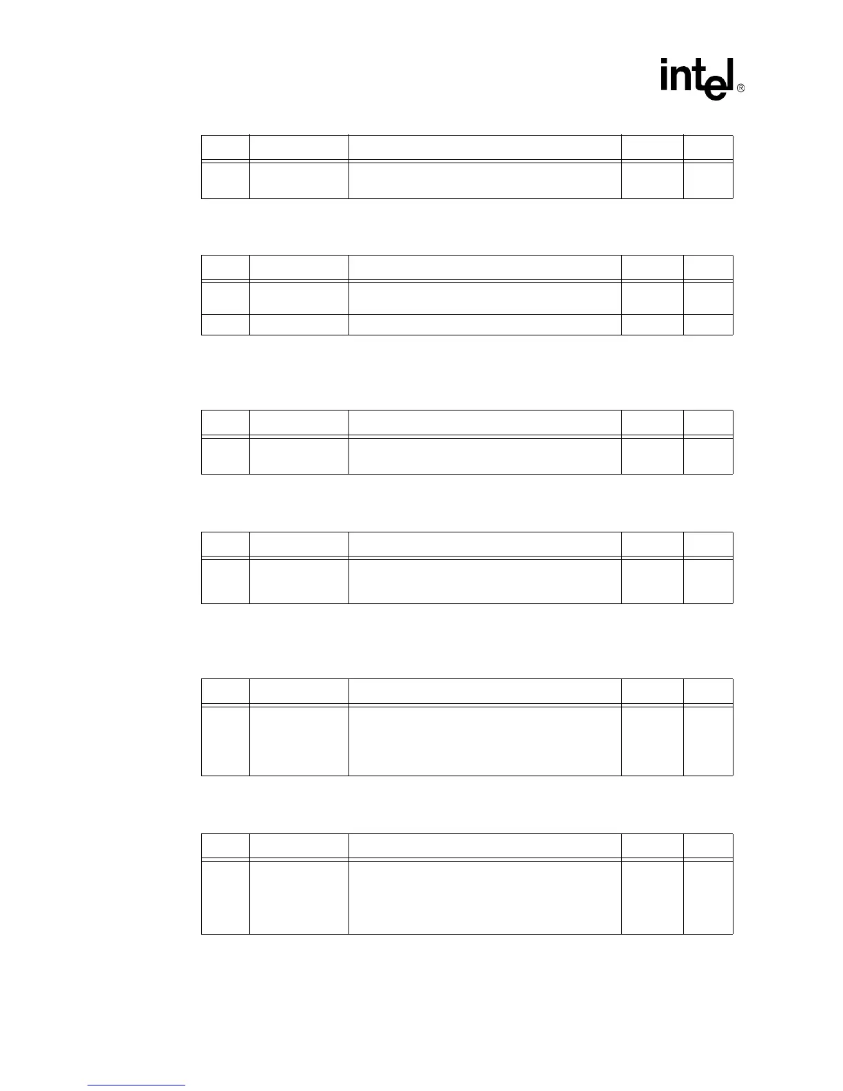
9.3.3 Register 18: PHY Address Register
9.3.4 Register 19: 100BASE-TX Receive False Carrier Counter Bit
Definitions
9.3.5 Register 20: 100BASE-TX Receive Disconnect Counter Bit Definitions
9.3.6 Register 21: 100BASE-TX Receive Error Frame Counter Bit
Definitions
9.3.7 Register 22: Receive Symbol Error Counter Bit Definitions
0 Jabber Function
Disable
1 = Jabber disabled
0 = Normal Jabber operation
0RW
Bit(s) Name Description Default R/W
15:5 Reserved These bits are reserved and should be set to a
constant ‘0’
0RO
4:0 PHY Address These bits are set to the PHY’s address, 00001b. 1 RO
Bit(s) Name Description Default R/W
15:0 Receive False
Carrier
These bits are used for the false carrier counter. -- RO
SC
Bit(s) Name Description Default R/W
15:0 Disconnect Event This field contains a 16-bit counter that increments for
each disconnect event. The counter freezes when full
and self-clears on read
-- RO
SC
Bit(s) Name Description Default R/W
15:0 Receive Error
Frame
This field contains a 16-bit counter that increments
once per frame for any receive error condition (such
as a symbol error or premature end of frame) in that
frame. The counter freezes when full and self-clears
on read.
-- RO
SC
Bit(s) Name Description Default R/W
15:0 Symbol Error
Counter
This field contains a 16-bit counter that increments for
each symbol error. The counter freezes when full and
self-clears on read.
In a frame with a bad symbol, each sequential six bad
symbols count as one.
-- RO
SC
Bit(s) Name Description Default R/W