1.3.1 MAX 10 Device Feature Options
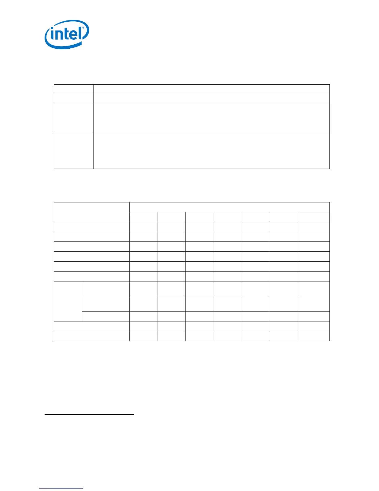
Table 3. Feature Options for MAX 10 Devices
Option Feature
Compact Devices with core architecture featuring single configuration image with self-configuration capability
Flash Devices with core architecture featuring:
• Dual configuration image with self-configuration capability
• Remote system upgrade capability
• Memory initialization
Analog Devices with core architecture featuring:
• Dual configuration image with self-configuration capability
• Remote system upgrade capability
• Memory initialization
• Integrated ADC
1.4 MAX 10 Device Maximum Resources
Table 4. Maximum Resource Counts for MAX 10 Devices
Resource Device
10M02 10M04 10M08 10M16 10M25 10M40 10M50
Logic Elements (LE) (K) 2 4 8 16 25 40 50
M9K Memory (Kb) 108 189 378 549 675 1,260 1,638
User Flash Memory (Kb)
2
96 1,248 1,376 2,368 3,200 5,888 5,888
18 × 18 Multiplier 16 20 24 45 55 125 144
PLL 2 2 2 4 4 4 4
GPIO 160 246 250 320 360 500 500
LVDS Dedicated
Transmitter
9 15 15 22 24 30 30
Emulated
Transmitter
73 114 116 151 171 241 241
Dedicated Receiver 73 114 116 151 171 241 241
Internal Configuration Image 1 2 2 2 2 2 2
ADC — 1 1 1 2 2 2
2 The maximum possible value including user flash memory and configuration flash memory. For
more information, refer to MAX 10 User Flash Memory User Guide.
1 MAX
®
10 FPGA Device Overview
MAX 10 FPGA Device Overview
6