2
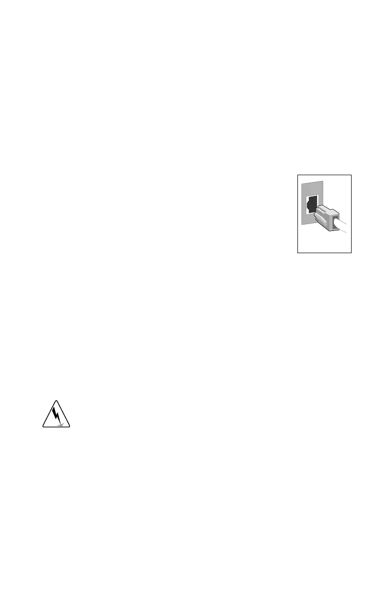
Connect the Network Cable
1 Connect a Twisted Pair Ethernet (TPE) network cable to the adapter as
shown below.
• For 100BASE-TX, your network cable must be Category 5, twisted-
pair wiring. If you plan to run the adapter at 100 Mbps, it must be
connected to a 100BASE-TX hub or switch (not a 100BASE-T4 hub).
• For 10BASE-T, use Category 3, 4, or 5 twisted-pair wiring. If you
want to use this adapter in a residential environment, you must use a
Category 5 cable.
NOTE
: Use a Category 5 TPE cable and an RJ-45
connector for this adapter. Do not use Category 3 wir-
ing at 100 Mbps. At 100 Mbps, connect to a TX hub,
not a T4 hub. For full duplex, see the section
Duplex
Mode
later in this guide. For more information on
100BASE-TX wiring requirements and limitations,
see
Fast Ethernet Wiring
in the
PCI Installation Tips
section later in this guide.
2 To configure the adapter, continue with the procedures specific to your
operating system outlined later in this guide.
Connect the Wake on LAN Power Cable
For the Wake on LAN (WOL) feature to work correctly, the adapter must be
connected to a continuous power source. This allows the PRO/100+ adapter to
“listen to” the network even when the computer is turned off. To install the
WOL power cable, carefully follow the procedure below.
WARNING
: Turn off and unplug power to the computer before installing the
WOL cable. The WOL connector on your motherboard is live when the
computer is plugged in to a power outlet. Failure to do so could damage the
adapter or computer. Likewise, always unplug the computer prior to removing
an adapter from the computer.
1 Make sure your computer is unplugged from the power outlet.
2 Locate the WOL connector on the PRO/100+ adapter. Attach one end of
the WOL cable to the adapter as shown in the diagram that follows.
Note that the connector is notched so as to prevent incorrect attachment.
P100se~2.fm Page 2 Tuesday, January 5, 1999 10:03 AM