Connectors and Jumper Blocks Intel® Server Board SE7520JR2
Revision 1.0
C78844-002
198
4 GND
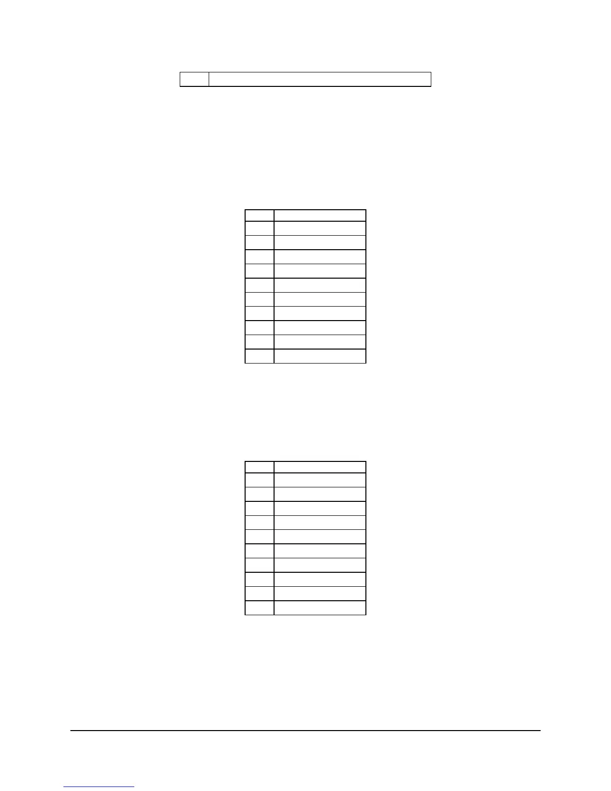
One internal 1x10 connector on the baseboard (J1F1) provides an option to support an
additional two USB 2.0 ports. This connector is used in both the Intel Server Chassis SR1400
1U and SR2400 2U bringing USB support to the control panel. The pin-out of the connector is
detailed in the following table.
Table 104: Internal 1x10 USB Connector Pin-out (J1F1)
Pin Signal name
1 USB_PWR(2)
2 USB_P2_L
3 USB_P2
4 Ground
5 Ground
6 USB_PWR(3)
7 USB_P3_L
8 USB_P3
9 Ground
10 Ground
For third party reference chassis, an internal 2x5 connector (J1G1) is supplied to provide an
additional two USB ports. The pinout for this connector is found in the following table.
Table 105: Internal 2x5 USB Connector (J1G1)
Pin Signal name
1 USB_PWR(5)
2 USB_PWR(4)
3 USB_BCK4_L
4 USB_BCK5_L
5 USB_BCK4
6 USB_BCK5
7 Ground
8 Ground
9 No Connect
10 No Connect
7.6 Fan Headers
The baseboard provides for several different system fan headers for use in Intel chassis as well
as custom and third party reference chassis.
 Loading...


