Intel® Server Board SE7520JR2 Design and Environmental Specifications
Revision 1.0
C78844-002
211
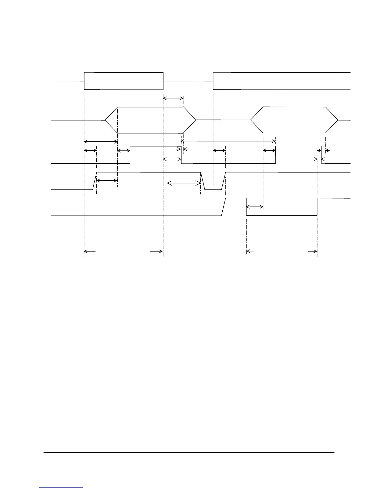
Figure 29. Turn On/Off Timing (Power Supply Signals)
8.2.14 Residual Voltage Immunity in Standby Mode
The PS supply should be immune to any residual voltage placed on its outputs (Typically a
leakage voltage through the system from standby output) up to 500mV. There shall be no
additional heat generated, nor stress of any internal components with this voltage applied to any
individual output, and all outputs simultaneously. It also should not trip the protection circuits
during turn on.
The residual voltage at the power supply outputs for no load condition shall not exceed 100mV
when AC voltage is applied.
AC Input
Vout
PWOK
5VSB
PSON
T
sb_on_delay
T
AC_on_delay
T
pwok_on
T
vout_holdup
T
pwok_holdup
T
pson_on_delay
T
sb_on_delay
T
pwok_on
T
pwok_off
T
pwok_off
T
pson_pwok
T
pwok_low
T
sb_vout
AC turn on/off cycle
PSON turn on/off cycle
T
5VSB
_
holdup
 Loading...


