The LightLEEDer EVO-INT Relay Panel is a microprocessor-based programmable lighting controller designed for commercial applications. It offers networking capabilities, allowing individual controllers to be linked together to form local or wide area networks, functioning as a single interface. The panel is UL and FCC approved.
Function Description
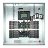
The LightLEEDer EVO-INT Relay Panel provides intelligent control over lighting loads. It integrates a controller board and an output board within a single enclosure. The controller board manages relays, monitors inputs, and facilitates communication. The output board houses the relays, power supply, and wiring terminals for line, load, neutral, and 0-10V dimming connections. Users can program each of the controller's inputs or data line devices to control any or all of the relay outputs.
Important Technical Specifications
Enclosure:
- Rating: NEMA 1 rated
- Mounting: Surface mounting with a screw cover door. Features 4 pre-drilled holes for easy wall mounting.
- Dimensions: 10" x 10" x 3"
- Capacity: Accommodates 4 to 8 integrated relays.
- Wiring: Configured with both Class 2 and high voltage sides for separated wire routing. Includes a high voltage barrier to separate Class 1 and Class 2 wiring.
Controller Board Components:
- Power Supply: Converts 24 VAC from the switcher supply into DC voltages for the controller and photocell.
- Relay Status LEDs: Indicate the state of each relay.
- Hardwired Inputs: Four inputs with 24VDC, supporting switches, occupancy sensors, or nurse call stations. Accepts momentary, momentary push button, or maintained switch types.
- Local LightSync Data Line Port: RJ45 port for direct connection of up to 17 remote devices.
- Photocell Port: RJ45 port for CAT-5 connection to an ILC Photo Sensor Head.
- Real-Time Clock: Provides time-controlled functions (time of day, day of week, day, daylight-saving time). Retains time for at least 45 days without power to the CPU.
- Non-Volatile Memory: Stores programming information, retaining data for up to 200 years without power to the CPU.
- Data Line Communications: RJ45 ports for communicating with other panels and LightSync data line devices.
- Relay Override Switches: "All On" or "All Off" switches for manual relay operation.
- Rotary Address Wheels: Used for setting the panel's address.
Output Board Components:
- Switching Power Supply: Converts 120/277 VAC line voltage to low voltages for the controller board.
- Terminals: Screw-down terminals for line, load, neutral, and 0-10V dimming connections.
- Relays: On-board relays available in 4 or 8 relay configurations. Each set of 4 relays is powered by a single 16A line voltage circuit.
- Line Input: Two independent line input connections (Line 1 for LD1-4, Line 2 for LD5-8). Combined output amperage for each set of four relays cannot exceed 16A.
- Voltage Rating (HV): 12AWG Copper conductors rated 75 Deg. C. Torque: 4.4 LB/IN.
- Voltage Rating (LV): 16AWG Copper Conductor rated 75 Deg. C. Torque: 1.7 LB/IN.
- Dimming Circuits: All Class 2 0-10V Dimming Circuits should use Type CL3, CL3P, CL3R, or equivalent conductors.
Environmental Considerations:
- Operating Temperature: 0 to 50° C (32°-122°F).
- Humidity: 10 to 90% non-condensing.
- Atmosphere: Non-explosive/corrosive.
- Installation: Stationary.
Network Cable Run Distance Detail (LightSync™ Network):
- Total Data Line Overall Distance: May not exceed 3000 feet without a Power Supply Repeater (PSR). A PSR extends the data line.
- Total Number of Devices (ILC panels and LightSync devices): 32 without a PSR. A PSR adds 31 more devices (PSRs count as a device).
- Total Number of LightSync Devices Powered: A controller panel can power its maximum LightSync devices without a Power Supply (PS), PSR, or LightSync Hub. Each PS, PSR, or LightSync Hub can power up to 20 additional LightSync devices.
- Total Power Cumulative Distance: May not exceed 2000 feet if powered by an ILC panel, or 3000 feet if powered by a PS, PSR, or LightSync Hub.
- Cable Type: Standard Category 5, 5E, or 6 cable with RJ45 connectors. Plenum-rated cable required for plenum runs. Underground-rated cable with a 12AWG solid Cu wire grounded at one end and surge suppressors for underground runs.
LightSync EVO-4X/8X Expansion:
- Capacity: The LLEVO-INT can operate up to 20 total relays, including on-board relays.
- Connection: Connects to the "Local" port of the LLEVO-INT Controller to the "In" port of the first 4X/8X board, and the "Out" port to each subsequent LightSync device.
Usage Features
- Programmability: Microprocessor-based, allowing flexible programming of inputs and data line devices to control relay outputs.
- Networking: Supports local area networks (LAN) and wide area networks (WAN) with up to 254 panels using a network controller. Panels and LightSync devices connect via standard CAT-5 cable with RJ45 connectors.
- Integrated Design: Combines controller and output functions in a single enclosure for streamlined installation.
- Manual Override: "All On" and "All Off" push buttons for manual control of all relays.
- Dimming Control: Supports 0-10V dimming outputs for compatible lighting loads.
- External Inputs: Connects to various external devices like switches, occupancy sensors, and nurse call stations.
- Photocell Integration: Dedicated RJ45 port for connecting an ILC Photo Sensor Head for daylight harvesting.
- Real-Time Clock Functions: Enables time-based scheduling, including time of day, day of week, and daylight-saving adjustments, as well as astronomical parameters for sunrise/sunset control.
- Software Configuration: Programmed using ILC LightLEEDer Software (LL Pro Single Panel or LL Pro Network Configuration Software).
Maintenance Features
- Pre-Installation Checklist: Comprehensive checklist to ensure proper unpacking, mounting, wiring, and initial setup.
- Cable Testing: Emphasizes testing all CAT-5 cables with an appropriate cable tester for shorts, opens, and inducted voltage prior to connection.
- Clear Memory Function: Critical step before programming to eliminate unwanted mapping. Accessible via a hidden menu in the virtual keypad of the ILC LightLEEDer Software.
- Visual Inspection: Recommends visual inspection of RJ45 crimps and high voltage connections.
- Cable Management: Guidelines for proper cable installation, including maintaining twists, gradual bends, using cable ties, avoiding excessive force, using lubricant, and separating low voltage from high voltage wiring to preserve warranty.
- Documentation: Encourages labeling every termination point and documenting cable distances on the provided riser for easier troubleshooting and future modifications.
- Technical Support: ILC provides documentation, videos, quick installation guides, quick programming guides, and technical telephone assistance.