13
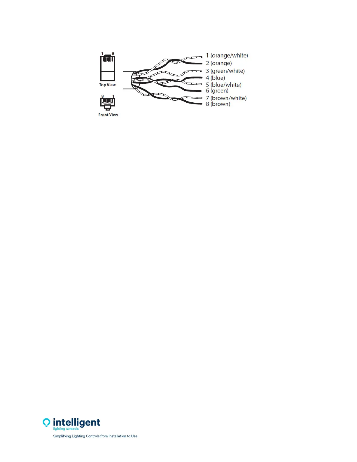
Figure2.4–RJ45CableTerminationDetail
Testeverycablepriortoinstallationforshorts,opens,andinductedvoltage.Besurenottoconnectyour
testertoacableconnectedtoanyhardwareasdamagemayoccur.
2.3.6ConnectCable
Aftercablesaretested,theycanbepluggedintothepanelsanddevices.Cablesstartatthe“Out”port,
gotothenextpanelordeviceandentersthe“In”port.Thisiscontinueduntilalldevicesareconnected.
2.4 Pre‐Power‐UpChecklist
☐Verifyallribboncablesbetweencontroller/outputboardsarewellseated.
☐Verifyallhighvoltagewiresareterminatedandthehighvoltagebarriersisinstalled.
☐Verifyalldatacables,sensorwires,dimmingwires,inputwiresareterminatedproperly.
2.5Power‐UpandCheckOut
2.5.1Power‐Up
ThecontrollerwillturnononcetheLine1andNeutralwiresareterminatedandthecircuitisenergized.
ThepowerLEDlocatedinthelowerleftshouldlightup.
2.5.2VerifyRelayOperation
Withthecontrollerpowereduppressthe“ALLON”pushbuttonswitchlocatedonthelowerleftsideof
thecontroller;alltherelaysshouldturnON.Pressthe“ALLOFF”buttonandverifythatallrelaysturned
OFF.Therelayshaveanon‐boardLEDthatindicatestheirstate.
2.5.3ClearingMemory
Itisverycriticaltoclearthememoryinthecontrollerpriortoprogrammingtoeliminateanypossible
unwantedmapping.IntheILCLightLEEDerSoftware,connecttothepanelwithadiagnostictoolonthe
networkport.Onceconnected navigatetothevirtualkeypadonthe“Connect”screen.Fromthe
keypad/display
push“Edit”,thenscrolldownto“SpecialFunctions”,thenscrolldownto“Fir mwareRe‐
vision”,pressbothupanddownscrollbuttonssimultaneouslytoenterahiddenmenu,andthenscroll
downto“ClearAllMemory”.