DMX 512 CONTROLLER SERIES
Item
1
2
6
8
10
11
12
13
14
15
16
17
18
19
9
4
3
7
5
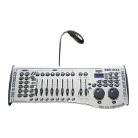
Button or Fader
Scanner select buttons
Scanner indicator LEDS
Page B Indicator LED
Program button
LCD display window
Mode Indicator LEDS
BankUpbutton
Bank Down button
Tap Display button
Blackout button
Midi/Rec button
Assign LED
Auto/Del button
Chaser buttons
Music/Bank Copy button
Channel faders
Scene select buttons
Page select button
Page A Indicator LED
Function
Fixture selection
Indicates the fixtures currently selected
Represents Ch 9~16 range selected
Used to enter programming mode
Status window displays pertinent operational data
Provides operating mode status,
(manual, music or auto)
Function button to traverse Scene/Steps in banks or chases
Incremental DMX values while button is active.FINE
Function button to traverse Scene/Steps in banks or chases
Decremental DMX values while button is active.FINE
This is a Tap-Sync during playback and during programming
changes the DMX value displayed in the LCD panel to percentages
Sets the shutter or dimmer value of all fixtures to 0 causing
all light output to cease
Activates MIDI external control and also used to confirm the
record/save process
Indicated the controller is in Channel assign mode during the
initial setup of the controller
IUsed to activate Auto mode and as the delete function key during
programming
Chase memory1~6
Used to activate Music mode and as the copy
command during programming
For adjusting DMX values, Ch 1~8 can be adjusted
immediately after pressing the respective scanner
select button, Ch 9~16 after pressing the Page
select button
Universal bump buttons representing scene
location for storage and selection
In manual mode, press to toggle between pages
of control or to select both pages simultaneously.
Both LEDS on will allow control of both lower and
upper range channel.
Represents Ch 1~8 range selected,
Tap A, B then B again to control both pages
simultaneously.
Tip!
DMX-240A USER MANUAL
4/20
 Loading...