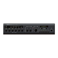
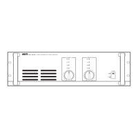
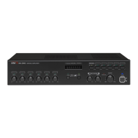
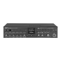
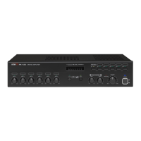
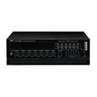
PA-2000/PA-4000/PA-2000R/PA-4000R Public Address Amplifier
4. Chime Button
Pressing this switch activates the chime circuitry.
5. Master Volume
This knob controls the overall volume of the amplifier’s output signal.
6. CH6 / Phono Volume
This knob controls the volume of Channel 6 or Phono Input, as selected by the
associated rear panel switch.
7. CH1-CH5 Volume
These knobs control the output volume of Channels 1 - 5.
8. Channel 1 Input
This is an input jack for Channel 1. Inserting a connector into this front-panel jack
will override (disconnect) the signal connected to the rear-panel CH1jack.
9. Graphic Equalizer
Each slider controls the cut (decreased gain) or boost (increased gain) for its
associated frequency band. The middle position indicates flat response (no cut or
boost). Moving the slider upwards increases that frequency’s gain, while moving it
down decreases the level of that frequency.
10. Protection Indicator
This LED indicates the state of the amplifier’s protection circuitry. When the
Protection LED is on (illuminated), the protection circuitry is active, indicating that
the unit is not operating normally. This is typically due to overheating or power
limiting. Please check the Input and Output condition of the amplifier.
11. Output Level Display
This 10-segment LED meter indicates the amplifier’s output level in RMS.
12. Tuning Frequency Display (PA-2000R/PA-4000R Only)
This LCD displays the currently selected frequency of the AM/FM tuner.
13. Tuner Power-On Switch (PA-2000R/PA-4000R Only)
To switch the AM/FM tuner on, press this switch
14. Band Selector Switch (PA-2000R/PA-4000R Only)
This switch selects the frequency band for the AM/FM Tuner. Pressing it selects
between AM band, FM band, or FM Mute.
15. Address Select Switches (PA-2000R/PA-4000R Only)
These switches are used to recall previously stored radio frequencies. The eight
switches can store and recall up to 16 frequencies within their A and B banks.
16. SHIFT Switch (PA-2000R/PA-4000R Only)
This switch, used in conjunction with the Address Select Switches (see 15 above),
selects between the two (A and B) banks of memory locations for preset radio
frequencies.
8