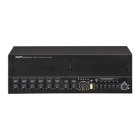
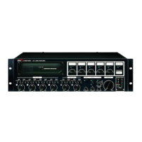
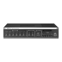
PAM-60/PAM-120 Public Address Amplifier
12. AC Power Input
Connect a standard three-pin AC cable to this connector.
13. Ext Mute
When these two terminals are shorted by wired remote, signals from Input
Channels 3-6 and any optional modules are muted. Signals from Channel 1,
Channel 2, Link In and Chime are not muted.
14. Ext Chime
When these two terminals are shorted, the four-tone chime circuitry is activated.
15. Telephone Input Terminals
These terminals can be connected to a telephone exchange system for paging
purposes.
NOTE: When an active signal is sent through the telephone input, all other input
signals except for AMP IN are muted.
16. Music-On-Hold Terminals (PAM-T AM/FM Tuner Module Only)
These terminals, along with the Telephone Input Terminals (15), are used for
connecting with an external telephone system. When used with the optional
PAM-T module, these terminals supply music-on-hold to the telephone system.
NOTE: When the tuner is switched on, signal from the tuner is constantly sent to
these terminals, and is unaffected by the Master Volume or the PAM-T’s volume
control.
17. Speaker Output Terminal Strip
Connect up to five individual speakers to this strip.
Impedances for 4, 25V, 70V and 100V/250V operation are shown below.
Connect speakers whose combined impedance is equal to or higher than the
rated output impedance, as shown below.
MODEL 4Ω 25V 70V 100V/250V
PAM-60 15.5V 10.5 83 Ω 165 Ω
PAM-120 22V 5.2 42 Ω 83 Ω
18. Impedance Selector
Selects between high impedance operation at 70V or 100V distributed systems.
Note that when speakers are connected to the 4 terminal, this switch is inactive.
19. Antenna Connector (Optional)
This terminal is used to connect the antenna, when used with the optional PAM-T
AM/FM Tuner module.
11