Page 5
Power Supply
Power is supplied either with 230VAC/110VAC alternating current or with a PoE-capable device IEE 802.af of
power class 3 (3= up to 13 Watt). A version for low-voltage operation with 12VDC/VAC to 30VDC/VAC is optionally
available. We recommend 18VDC (order number of plug-in power supply unit: 41-10063).
See chapter "Connections"
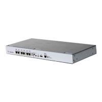
Controller Housing
This chapter provides information on the intended use of the sockets, the functions of the LEDs and
switches and the installed electronics.
Sockets
The following sockets are used for connecting devices:
• 1x RJ45 socket with RS232 interface for connection to a service device
• 1x RJ45 socket with RS232 interface for connection to the host
• 1x RJ45 socket with RS485 interface for connection to the host
• 3x RJ45 socket with RS485 interface for connection of BUS data cables with slave terminals
• 1x RJ45 socket for connection to Ethernet network
• 1x USB socket. The socket will be used for future applications
LED Displays
Seven LEDs indicate the controller operating statuses:
Data exchange with slave terminal on BUS 1
Data exchange with slave terminal on BUS 2
Data exchange with slave terminal on BUS 3
Application started, controller ready for operation
AKKU is switched on and being charged (only devices with emergency power
supply.
Network connection with 100 Mb/ network connection with 10 Mb
Reset Button
The RST button ends active processes and triggers a reboot.
Kaltst Switch
This switch is used to delete saved data and set default parameters.
SW Switch
The SW switch is used to set the standard IP address 172.18.70.52 and temporarily store the IP address set.
Further information on activating the switching functions can be found in chapter: >Setting Default
Parameters<
AKKU Switch
The AKKU switch is for switching the accumulator ON/OFF on devices with optional emergency power supply. After
the switch is set to ON, the AKKU LED lights up and indicates that the accumulator is charging.
1
LED can also flicker.