Page 6
Controller Back Side
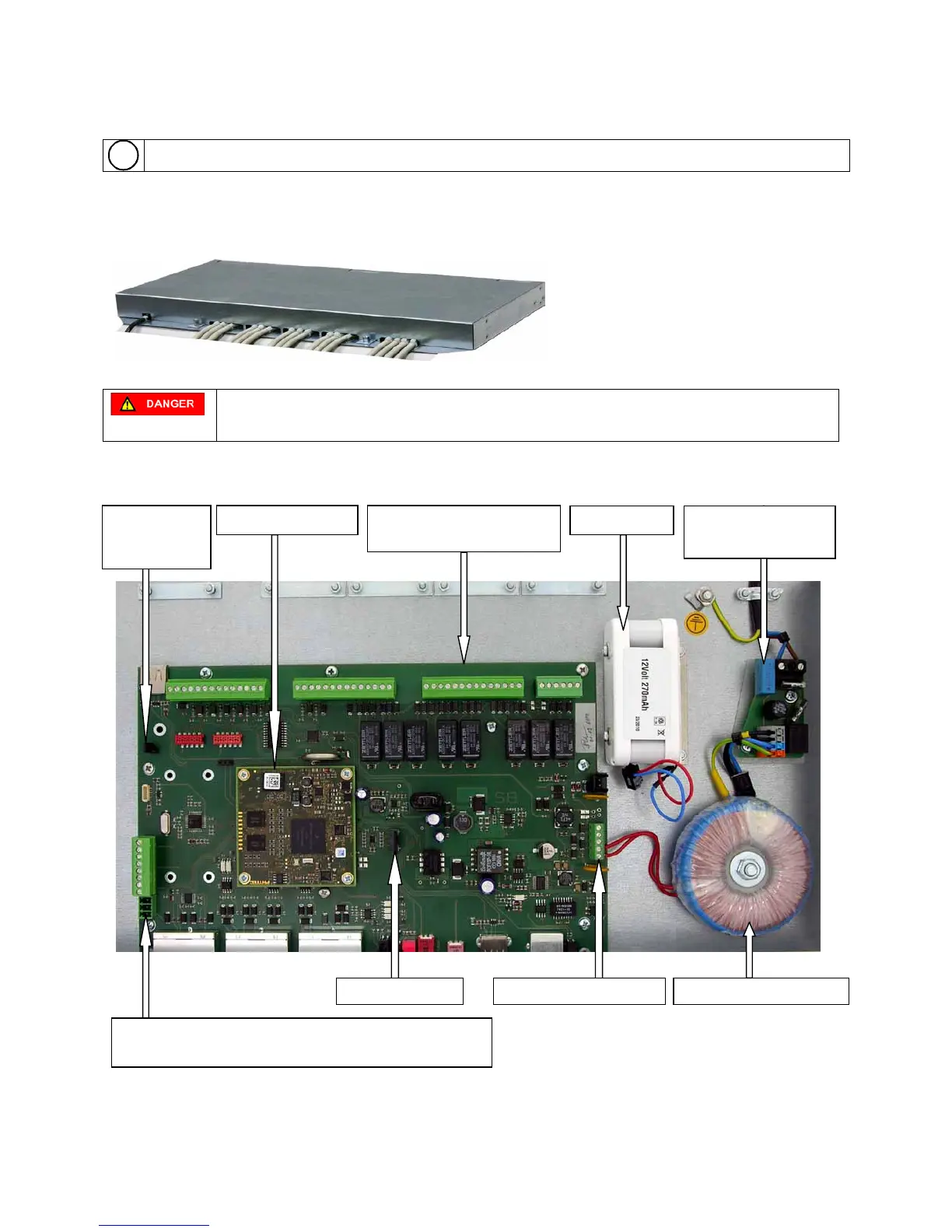
This chapter provides information on the controller back side and the installed electronics.
The mains cable with Schuko plug, the openings for inserting signal cables and cable strain reliefs with cable ties
as well as the two screw nuts for fastening the cover are on the back side of the unit.
L-brackets and retaining plates can be screwed to the sides for mounting into 19" rack systems.
Danger of electric shock.
People can be seriously hurt or killed through physical contact with 230-volt electricity.
Unplug the Schuko plug prior to opening the housing cover.
Electronic Assembly Units:
Figure 2: Terminal controller with installed electronics.
Interface board with screw
connectors
KL.7 3-pin screw connector for RS232 service cable
KL.6 screw connector for RS485 BUS data cable