INSTALLATION
Mounting Actuator on Top of Valve
1. Unscrew hold-down knob and remove handle from
valve shaft. Save knob and handle for later use.
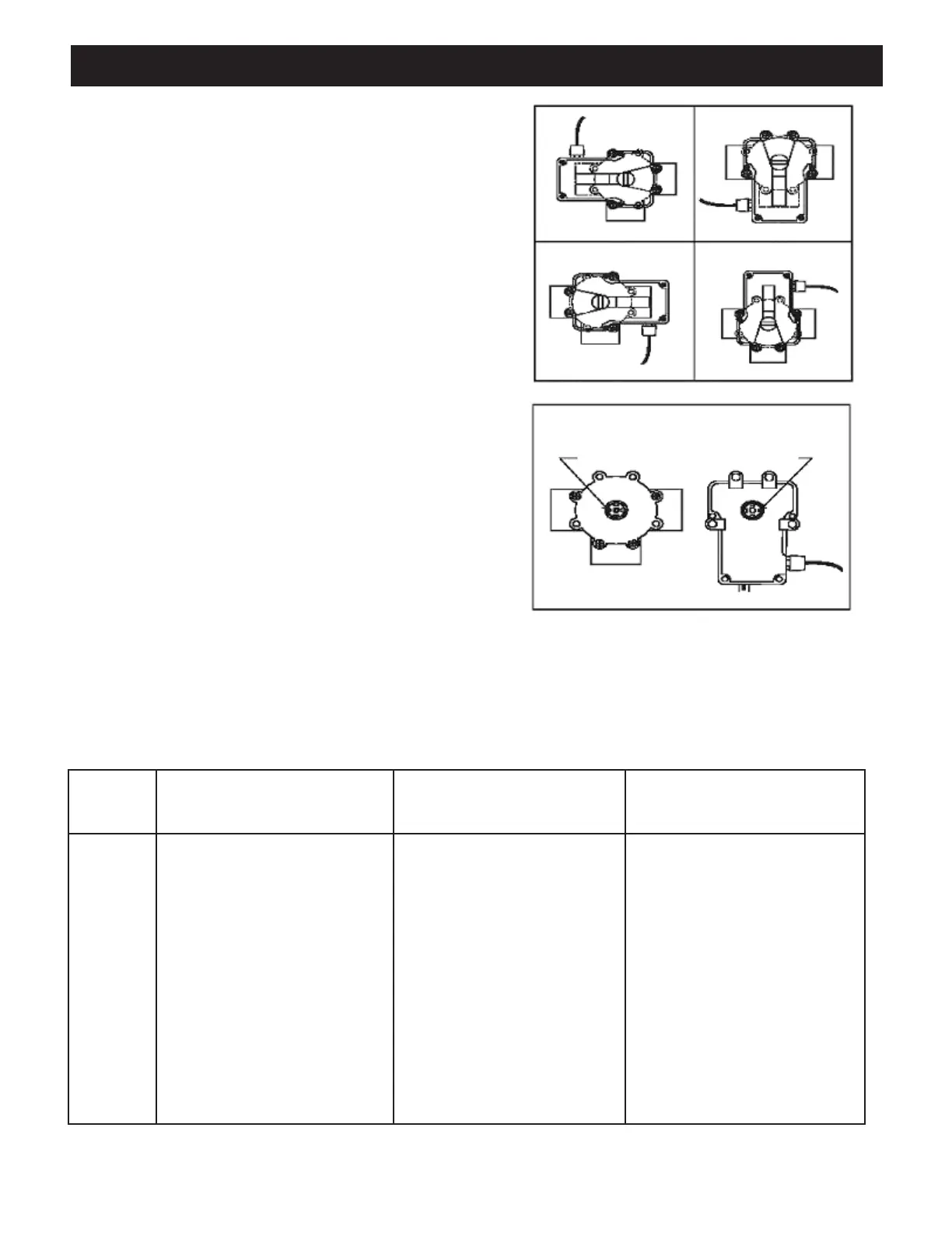
2. Depending on mounting position selected, (See
figure 3), remove (4) Philip head screws from
valve body. (See figure 1).
3. Turn Actuator over and note that one of the four teeth
of the output drive is slightly smaller. Place Actuator
over the valve shaft such that the small tooth engages
with the small slot in the valve shaft. (See figure 4).
4. Rotate the Actuator, engaged with the valve shaft
until Actuator posts line up with the four holes
(See step 2 above) in valve body.
5. Attach Actuator to valve, using the four long
stainless steel screws - furnished.
6. Reassemble handle to Actuator shaft using the
hold-down knob set aside in step 1.
7. Connect power supply cord to a CLASS 2 CIRCUIT
ONLY, rated 24V nominal, 4A or 100VA maximum.
I
II
IIII IV
A
A
A
A
B
B
B
B
C
C
C
C
Place actuator on valve so small tooth aligns
with small slot.
SMALL SLOT SMALL TOOTH
VALVE
BOTTOM
VIEW OF
ACTUATOR
Figure 3. Mounting Positions.
Figure 4. Actuator Mounting.
2
Resetting The Cams
NOTE: Before resetting cams, read instructions on page 3. Always rotate the actuator shaft to “0” mark on
each cam.
Cam Setting Chart
Actuator Port, Water Enters/Exits Valve Cam Setting Port, Water Enters/Exits Valve
Position (Common Port) Top Cam Bottom Cam Port or Port
I* A 90 180 B C
I B 90 270 A C
I C 180 90 A B
II* A 180 90 B C
II** B 0 0 A C
II C 90 180 A B
III* A 90 180 B C
III B 270 90 A C
III C 0 270 A B
IV* A 0 270 B C
IV B 180 180 A C
IV C 270 0 A B
*Two Port Valve Settings
**Standard Position