10 Serial/Industrial Interface Kit Installation Instructions
Chapter 2 — Physical Installation
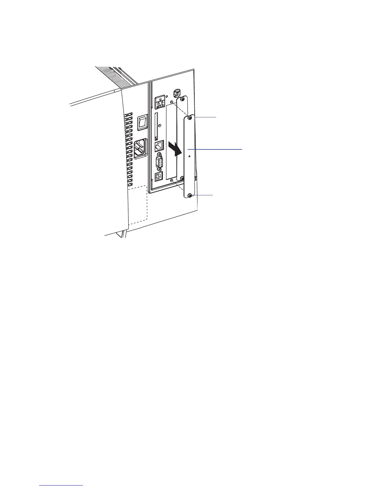
• Remove the two #T10 Torx screws that hold the cover plate. Always
start with the inner one. Remove the cover plate.
• Save the cover plate for possible later use. Keep the screws.
• Remove the #T20 Torx screw fi tted on the hexagonal spacer at the
center of the CPU board. Keep the screw.
• If reconfi guration of the interface board is required, fi t or remove
circuits and straps according to the descriptions in Chapters 3 and 4.
• Attach the fl at cable included in the kit to connector J62 (marked
“EXP BOARD”) on the CPU board (see illustration on page 12).
#T10 Torx screw
Cover plate
#T10 Torx screw