Serial/Industrial Interface Kit Installation Instructions 11
Chapter 2 — Physical Installation
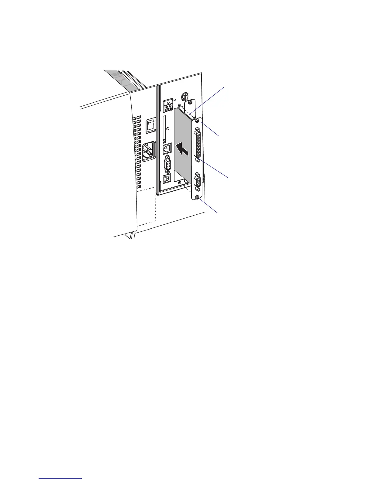
• Insert the interface board with the component side facing right, as
seen from behind.
• Attach the interface board to the printer’s rear plate using the two
screws left over when you removed the original cover plate.
• Using the #T20 Torx screw you previously removed, attach the inter-
face board to the hexagonal spacer on the CPU board (see next page).
If you are installing an interface board in the outer slot, you need to
remove the screw that holds the inner board and replace it with the
spacer included in the kit. e secure the outer board to the spacer
with the screw (see illustration on the next two pages).
• e kit contains two fl at cables, one with two connectors for use with
a single interface board and one with three connectors for use with
double interface boards. Connect the appropriate fl at cable to connec-
tor P1 on the interface board, also see the next two pages.
Interface board
Component side
#T10 Torx screw
#T10 Torx screw