16 Serial/Industrial Interface Kit Installation Instructions
Chapter 2 — Physical Installation
• Save the cover plate(s) for possible later use. Keep the screws.
• Remove the #T20 Torx screw fi tted on the hexagonal spacer at the
center of the CPU board. Keep the screw.
• If necessary, reconfi gure the interface board by fi tting or removing
circuits and straps according to the descriptions of each board later in
this chapter.
• Attach the fl at cable included in the kit to connector J62 (marked
“EXP BOARD”) on the CPU board (see illustration on the next
page).
• Insert the interface board with the component side facing right, as
seen from behind.
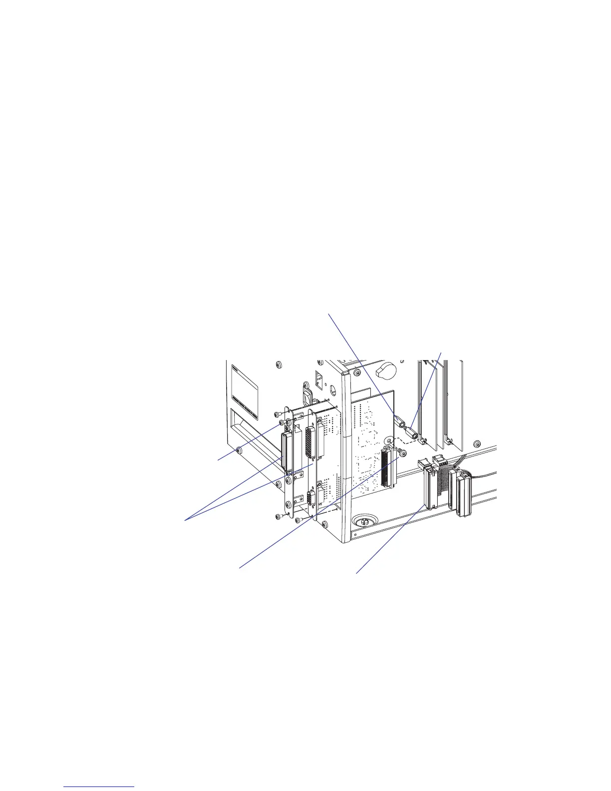
Illustration shows installation of one IEEE 1284 and one Serial/Industrial interface
board.
• Installation of one board: Attach the interface board in the innermost
slot in the printer’s rear plate using the two screws left over when you
removed the original cover plate. Using the #T20 Torx screw you
previously removed, attach the interface board to the hexagonal spacer
at the center of the CPU board.
Connect to J62
Interface boards
Spacer
(only in
case of two
boards)
Existing
spacer
#T20 Torx screw
#T10 Torx screw (2 + 2)