$16#PBSE
*OOFS*OUFSGBDF#PBSE
4QBDFSGSPNLJU
4QBDFSFYJTUJOH
4DSFXFYJTUJOH
0VUFS*OUFSGBDF#PBSE
$BCMF
$16#PBSE
*OOFS*OUFSGBDF#PBSE
4QBDFSFYJTUJOH
4DSFXFYJTUJOH
$BCMF
Serial/Industrial Interface Kit Installation Instructions 17
Chapter 2 — Physical Installation
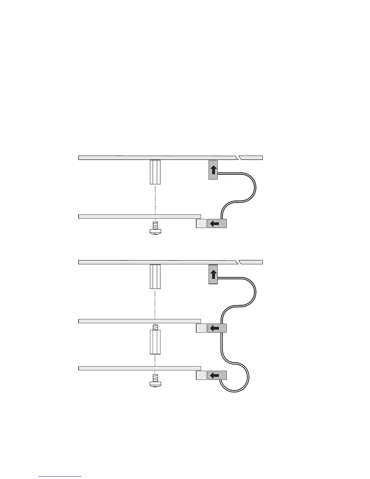
• Installations of two boards: First install the inner board, then the outer
one. Put the hexagonal spacer included in the kit between the inner
and the outer interface board, and fi nally secure the outer board with
the screw.
• e kit contains two fl at cables, one with two connectors for use with
a single interface board and one with three connectors for use with
double interface boards. Connect the appropriate fl at cable to connec-
tor P1 on the interface board, as illustrated below.
• e fl at cable should run as illustrated below.
• Put back the cover over the electronics compartment.
• Connect the communication cables to the connectors on the printer’s
rear plate.