17
• The different components of the system are controlled by the following digital outputs of
the PLC:
Output N°
Function
1 hydraulic pump
2 vacuum pump
3 heating
4 solenoid valve
6 signal light for low oil level in the vacuum pump
• The digital input signals and outputs can be either ON (LED is light) or OFF (LED is
dark).
4.8. Other
• With the buttons [] (Temp. up) respectively [] (Temp. down) the switch off
temperature can be set.
• At achieving of the set temperature the preheater switches off, if the actual oil
temperature is again lower than the set temperature the preheater is switched on again.
Please note that the set temperature value is only a switch off criteria. It
cannot be assured that the oil temperature actually reaches that setpoint.
The surface area of the heating can be more than 70°C during
operation . Risk of burns!
• The humid air of the vacuum pump will be led through a moisture separator and then
emitted to the atmosphere.
The level of the reservoir should be checked daily.
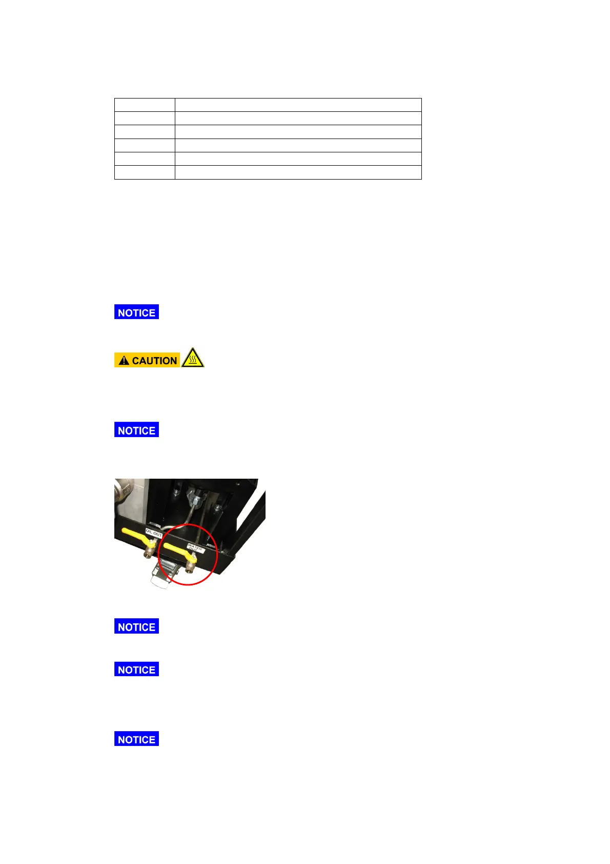
• The collected humidity in the condenser can be discharged with the ball valve
“Water out”
• Most of the separated water will leave the IFPM/S as humid air.
At lower water contents in the oil there will hardly be any water collected
in the condenser.
It is not a mistake if no water is collected in the separator. This only
indicates low water content or low temperature of the oil.
• The vacuum in the vacuum chamber can be adjusted with opening and closing the
throttle valve (5).
The optimum vacuum and the optimum temperature depend on the fluid
type which should be dewatered and on its condition. The vacuum should not be
higher than -0,9 bar and not lower than -0,6 bar.
• The actual flow rate depends on the following parameters: