103
CD
SAVE THESE INSTRUCTIONS
Page 11
(103CD) MODEL 8111 (MODEL 8110 + MODEL 51) DELUXE SALTWATER SYSTEM (SALT IN POOL) & FILTER PUMP ENGLISH 7.5” X 10.5” PANTONE 295U
12/25/2007
PPRROODDUUCCTT IINNFFOORRMMAATTIIOONN//SSPPEECCSS
Common salt (sodium chloride) is made up of two elements, sodium and
chlorine. During the installation of your Saltwater System/Filter Pump, a
measured quantity of salt is dissolved in the pool water to make it slightly
salty.This pool water is passed through the saltwater system’s electrolytic
cell to produce HOCL which is dissolved instantly in the water. The HOCL
instantly starts to destroy bacteria, algae and oxidizes other organic
materials.
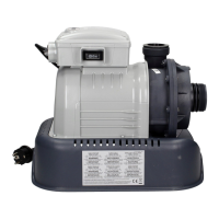
Key Saltwater System Parts:
• Power Supply
The power supply converts AC electrical current to a low voltage DC current. This
is required by the cell to perform the electrolysis that creates chlorine.
• Electrolytic Cell (with Titanium Plates)
The electrolytic cell contains bipolar titanium electrodes which perform the
electrolysis and produce liquid sanitizer (HOCL) when energized with DC
electricity. Sanitizer is generated when pool water containing salt passes through
the cell. The sanitizer production can be varied by changing the number of hours
the saltwater system is operating each day. The saltwater system has a built-in
self cleaning cycle that operates every twenty hours without interrupting sanitizer
production.
• Flow Sensor
The flow sensor protects the electrolytic cell and ensures there is adequate water
flowing through the cell. When the water flow drops below minimum flow rate, the
electrolytic cell will automatically shut down to protect the titanium plates. A safety
buzzer will sound and the LED display panel will show a signal code (see “LED
Code Chart”) indicating the problem.
• Electronic Control Station
The electronic control station contains an LED display panel and a set of
pushbuttons to program the saltwater system operating hours. It also monitors the
different parameters such as salt level, water flow and the electrolytic cell activity.
If any deviation from the norm occurs then a buzzer will sound and the LED
display panel will show a signal code (see “LED Code Chart”) indicating the
problem.
PRODUCT SPECIFICATIONS
Power: 110 - 120 Volt
Amperage: Saltwater System - 2.5 A; Filter Pump - 2.6 A
Wattage: Saltwater System - 250 W; Filter Pump - 280 W
Ideal Salt Level: 3000 ppm (parts per million)
Maximum Sanitizer Output/hour: 24 grams/hour
Limited Warranty: 2 Years (see “Limited Warranty”)
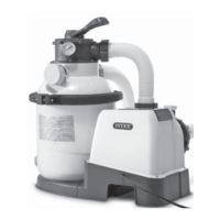
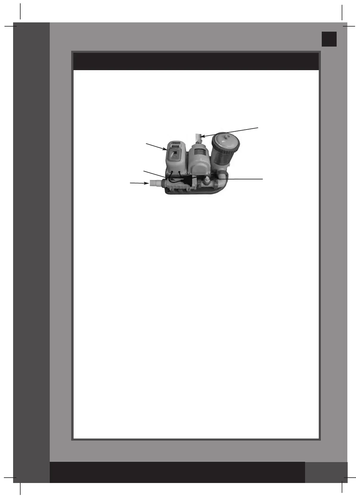
HOW SANITIZER IS GENERATED
Water Outlet
Water Inlet
Flow Sensor
Electronic Control
Station
Electrolytic Cell
(with Titanium
Plates)
 Loading...