
S
Sara OrtizJul 31, 2025
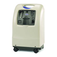
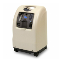
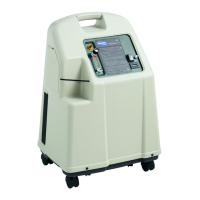
What to do if Invacare IRC5PO2 has power loss and internal status indicators are off?
- CcardenasdavidJul 31, 2025
If your Invacare Medical Equipment experiences a power loss, with both the red and green internal status indicators off, ensure the unit is plugged in. Turn the power switch to the ON position (I /) to begin recharging the device.