EasyManua.ls Logo

Invacare IRC5P - Service Manual

Invacare IRC5P
88 pages
Print Icon
To Next Page IconTo Next Page
Loading...
Service Manual
DEALER: Keep this manual. The procedures in this manual MUST be
performed by a qualified technician.
For more information regarding
Invacare products, parts, and services,
please visit www.invacare.com
Perfecto
2
Oxygen Concentrator
(HomeFill
®
Compatible)
Model IRC5PO2 (Sensored)
Model IRC5P (Non-Sensored)

Table of Contents

Other manuals for Invacare IRC5P

Questions and Answers

  • A
    Andrea ObrienAug 15, 2025
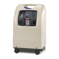
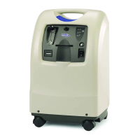
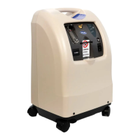
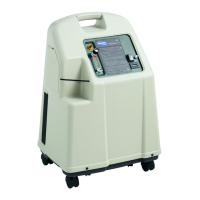
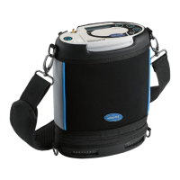
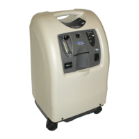
    What to do if my Invacare Oxygen Equipment alarm is continuous?
    • M
      Matthew KnightAug 15, 2025
      If your Invacare Oxygen Equipment is emitting a continuous alarm, it could be due to several reasons: * The unit may be overheating because the air intake is blocked. To resolve this, remove and clean the cabinet filters and ensure the concentrator is at least three inches away from walls, draperies, or furniture. * There might be insufficient power at the outlet. Avoid using extension cords and try a different electrical outlet or circuit. * In some cases, internal repairs may be required, and you should call your Service Provider.
  • R
    Richard MooreAug 18, 2025
    Why is my Invacare Oxygen Equipment beeping with short beeps and long pauses?
    • J
      jenniferphamAug 18, 2025
      If your Invacare Oxygen Equipment is emitting short beeps followed by a long pause, it indicates a main power loss. Here’s what you can do: 1. Ensure the power cord is properly plugged into the outlet. If it isn't, insert the plug into the outlet. 2. Check if there is power at the outlet. Inspect the house circuit breakers or fuses. If the problem continues, try using a different outlet. 3. If a circuit breaker has tripped, call your Service Provider.
  • C
    Carrie DavisAug 21, 2025
    What to do if my Invacare Oxygen Equipment is beeping rapidly?
    • L
      Lisa MorrisAug 21, 2025
      If your Invacare Oxygen Equipment is alarming with rapid beeps, it typically indicates a low flow. Here’s how to address it: 1. Check for any kinks or blockages in the tubing, cannula, or humidifier. If you find any, correct, clean, or replace the item. Afterward, turn the power off for 60 seconds and then turn it back on. 2. Verify that the flowmeter is not set at 0.5 L/min or less. If it is, reset the flowmeter to the prescribed flow rate. Note: If the prescribed flow rate is below 0.5 L/min, use the Pediatric Flowmeter IRCPF16 (Only with Perfecto 5).
  • W
    William MillerAug 25, 2025
    What to do if Invacare IRC5P Medical Equipment has power loss and internal status indicators are off?
    • T
      Tasha GloverAug 25, 2025
      If your Invacare Medical Equipment experiences a power loss, with both the red and green internal status indicators off, ensure the unit is plugged in. Turn the power switch to the ON position (I /) to begin recharging the device.
  • R
    Robert SerranoAug 27, 2025
    What to do if the Invacare IRC5P alarm is continuous?
    • D
      Dana ChandlerAug 27, 2025
      If the Invacare Medical Equipment alarm sounds continuously, it indicates a system failure. This may be due to the unit overheating because of a blocked air intake, insufficient power at the outlet, or internal repairs being required. Try the following: 1. Clean the cabinet filters or move the oxygen concentrator at least 12 inches away from walls, draperies, or furniture. 2. Avoid using extension cords and try a different electrical outlet or circuit. 3. If the problem persists, contact your service provider.
  • J
    Joseph TaylorSep 2, 2025
    What to do if Invacare Medical Equipment alarm sounds with rapid beeps?
    • V
      vtoddSep 2, 2025
      If your Invacare Medical Equipment alarm is sounding with rapid beeps, it indicates a potential obstruction. This could be due to an internal obstruction in the oxygen path, such as kinked or blocked tubing, cannula, or humidifier, or the flowmeter being set at 0.5 L/min or less. Here's how to address it: 1. Check for any kinks or blockages in the tubing, cannula, or humidifier. Correct, clean, or replace the affected item. After doing so, turn the power off for 60 seconds and then turn it back on. 2. Ensure the flowmeter is set to the prescribed flow rate. If the prescribed rate is below 0.5 L/min, use the Pediatric Flowmeter IRCPF16 (only with Perfecto2 5). Note: Using the pediatric flowmeter will deactivate the Potential Obstruction Alert.
  • D
    David BrownSep 5, 2025
    How to fix Invacare IRC5P Medical Equipment alarm with short beeps and a long pause?
    • N
      nicolelawrenceSep 5, 2025
      An alarm with short beeps and a long pause on your Invacare Medical Equipment indicates a main power loss. This could be due to the power cord not being plugged in, no power at the outlet, or a tripped circuit breaker. To resolve this: 1. Ensure the plug is fully inserted into the outlet. 2. Inspect the house circuit breakers or fuses. If the problem continues, try a different outlet. 3. Reset the circuit breaker. If it trips again, contact your service provider.
  • M
    Mary Gould DVMSep 12, 2025
    What does it mean if the green light is on and the yellow light is flashing on my Invacare Oxygen Equipment?
    • R
      Robert TurnerSep 12, 2025
      If your Invacare Oxygen Equipment shows a GREEN light with a YELLOW light flashing, it means internal repairs are required. Contact your Service Provider.
  • S
    Scott GravesDec 1, 2025
    Why is the yellow or red light illuminated on my Invacare IRC5P and what should I do?
    • A
      alexandra30Dec 1, 2025
      A YELLOW or RED light illuminated on your Invacare Medical Equipment indicates a system failure. This can be due to several reasons: * Low oxygen purity. * Kinked or blocked tubing, cannula, or humidifier. * Flowmeter set at 0.5 L/min or less. * Unit overheating due to blocked air intake. * Insufficient power at outlet. * Internal repairs required. Here's what you can do: 1. Clean or replace the filters. 2. Inspect for and correct any kinks or blockages in the tubing, cannula, or humidifier. Then, turn the power off for 60 seconds and back on. 3. Ensure the flowmeter is set to 1.0 L/min or more. 4. Clean the cabinet filters or move the concentrator at least 12 inches away from obstructions. 5. Avoid using extension cords; use a different electrical outlet or circuit. 6....

Summary

Special Notes and Safety Information

Signal Word Definitions

Defines signal words like DANGER, WARNING, and CAUTION for hazard identification.

Fire Hazard Warning

Highlights severe fire risk from ignition sources near oxygen.

Important Safeguards

Federal Law Restrictions

States device is restricted to sale/rental by physician order.

Fire Risk with Oxygen

Details fire risk from oxygen enrichment and ignition sources.

Electrical Safety and Handling

Covers avoiding water, unplugging fallen units, and proper handling.

Placement and Usage Precautions

Ensures proper unit placement, airflow, and tubing use for safe operation.

Radio Frequency Interference (RFI)

Advises caution regarding portable communications equipment near electronic devices.

General Safety Precautions

Lists safety rules including avoiding wet conditions, unattended operation, and proper use.

Installation and Sequence of Operation

Battery Free Power Loss Alarm Verification

Procedure to check the functionality of the Battery Free Power Loss Alarm.

Sequence of Operation

Describes the internal process of air intake, compression, and oxygen delivery.

SensO2 Oxygen Sensor Technology

Explains the Ceramic Zirconia Sensor technology for oxygen purity monitoring.

Operating Sequence

Details steps from power-on to stable oxygen production and sensor stabilization.

Pneumatic Diagram

Troubleshooting Common Issues

Normal Operation and Power Loss

Addresses issues related to normal status indicators and power loss scenarios.

Circuit Breaker and Power Cord Issues

Troubleshooting steps for tripped circuit breakers and damaged power cords.

Internal Status Indicators and Faults

Guides on interpreting internal status indicators for various system failures.

High Pressure and Valve Malfunctions

Troubleshoots high pressure conditions and 4-way valve operational failures.

Unit Not Operating or Low Concentration

Diagnoses problems with unit startup, alarms, and low oxygen concentration.

Flowmeter and Timing Issues

Addresses fluctuating flow, timing adjustments, and regulator settings.

Excessive Noise and Filter Problems

Troubleshoots loud unit operation, dirty filters, and compressor issues.

Unit Overheating and Line Voltage Surges

Diagnoses overheating causes and issues related to excessive line voltage.

Oxygen Purity and Alarm Conditions

Guides on troubleshooting low oxygen purity and specific alarm conditions.

System Leaks and Check Valve Failures

Addresses system leaks and issues with defective check valves.

Cabinet Maintenance

Removing the Cabinet Assembly

Step-by-step instructions for safely removing the main unit cabinet.

Preventive Maintenance Schedule

Cleaning the Cabinet Filter

Procedure for cleaning the primary air intake filter for optimal airflow.

Replacing the Outlet HEPA Filter

Instructions for checking and replacing the HEPA filter at the oxygen outlet.

Replacing the Compressor Inlet HEPA Filter

Guide for replacing the air filter before the compressor for protection.

Replacing the Muffler Assembly

Steps for replacing the exhaust muffler to reduce operational noise.

Cleaning the Heat Exchanger

Procedure for cleaning the heat exchanger to maintain thermal efficiency.

Compressor Service and Rebuilding

Replacing the Compressor Assembly

Procedure for removing and installing the entire compressor unit.

Replacing the Compressor Capacitor

Instructions for replacing the capacitor associated with the compressor motor.

Rebuilding the Thomas Model 2660 Compressor

Detailed guide for disassembling and rebuilding the specific compressor model.

Removing Compressor Heads and Valve Plates

Steps for disassembling compressor heads and valve plates for service.

Rebuilding Compressor Components

Guides on servicing the fan, connecting rod, eccentric, and piston cup.

Replacing O-rings and Valve Keeper Strips

Procedure for replacing O-rings and keeper strips on valve plates.

Replacing Exhaust Valve Flappers and Gaskets

Instructions for replacing exhaust valve flappers and valve plate gaskets.

Reassembling Compressor Gasket and Valve Components

Steps for installing new gaskets, valve flappers, and O-rings.

Reassembling Piston Cup and Connecting Rod

Instructions for correctly installing piston cups, retainers, and connecting rods.

Reinstalling Fan and Valve Plates

Procedure for reinstalling the fan and valve plates onto the compressor.

Reinstalling Compressor Heads

Steps for tightening compressor head screws in the correct sequence.

P.E. Valve Service

Replacing the P.E. Valve Assembly

Step-by-step guide for removing and installing the P.E. valve assembly.

Sieve Bed Replacement

Replacing Sieve Beds

Procedure for replacing sieve beds, emphasizing pair replacement and proper handling.

Check Valve Service

Replacing Check Valves

Instructions for correctly installing check valves, noting directional markings.

Regulator Adjustment and Replacement

Replacing the Regulator Assembly

Procedure for removing and installing the pressure regulator.

Adjusting Regulator Pressure

Steps for setting the correct output pressure using the adjustment screw.

Heat Exchanger Assembly Service

Replacing the Heat Exchanger Assembly

Instructions for removing and installing the heat exchanger assembly.

Control Panel Servicing

Removing and Replacing the Control Panel

Procedure for removing, servicing, and reinstalling the control panel assembly.

Cooling Fan Maintenance

Replacing the Cooling Fan

Detailed steps for removing and installing the cooling fan, noting orientation.

Printed Circuit (P.C.) Board Replacement

P.C. Board Handling Precautions

Safety precautions for handling P.C. boards, including grounding and static prevention.

Replacing the P.C. Board

Procedure for disconnecting wiring, removing, and installing a new P.C. board.

Transformer Replacement

Replacing the Transformer

Instructions for locating, disconnecting, and replacing the unit's transformer.

On;Off Switch Replacement

Replacing the On;Off Switch

Procedure for removing and installing the main power On/Off switch.

Flowmeter Replacement

Replacing the Flowmeter

Steps for removing and installing the flowmeter on the control panel.

Hour Meter Replacement

Replacing the Hour Meter

Procedure for removing and installing the hour meter.

4-Way Valve and Manifold Assembly Service

Replacing the 4-Way Valve and;or Manifold Assembly

Detailed steps for replacing the 4-way valve and manifold assembly.

Replacing Pilot Valve Poppets and O-Rings

Instructions for replacing pilot valve poppets and O-rings within the assembly.

Oxygen Purity Indicators and Alarms

SensO2 Alarm Indicators

Explanation of indicator lights and alarms for oxygen purity monitoring.

LX Models Indicator Light Explanation

Specific indicator light functions for LX model units.

Timing Adjustments

Autotuning Procedure

Steps for performing automatic P.E. valve timing adjustment.

Manual Tuning Procedure

Instructions for manually adjusting the P.E. valve timing switch.

Leak Testing Procedures

Performing a Leak Test

Methodology for testing pneumatic connections for leaks using solution.

4 Way Valve Function Test

Procedure to test the 4-way valve's operation and leakage tolerance.

Alarm System Testing

Power Loss Alarm Test

Procedure to test the audible alarm when power is removed.

Low Pressure Test

Tests for low pressure conditions and the activation of the low pressure alarm.

Time-Out Test

Procedure to test the Time-Out Failure alarm functionality.

High Pressure Test

Tests for high pressure conditions and related alarm sequences.

Oxygen Sensor Alarm Test

Procedure to test the oxygen sensor alarm for purity levels.

P.E. Valve Coil Test

Test to check for P.E. valve coil failure by simulating an alarm condition.

Sieve Bed Pressure Testing

Disassembly for Pressure Check

Steps for disassembling the unit to access sieve beds for pressure testing.

Pressure Testing Procedure

Instructions for connecting gauges and measuring system pressures.

Limited Warranty Information

Invacare IRC5P Specifications

General IconGeneral
BrandInvacare
ModelIRC5P
CategoryMedical Equipment
LanguageEnglish

Related product manuals