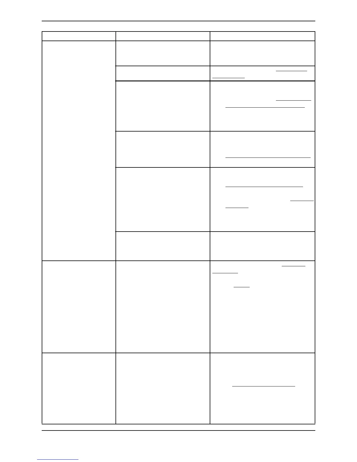
SECTION 4—TROUBLESHOOTING
Part No 1148070 21 Perfecto
2
™
Unit Overheats: Base exhaust vent plugged or
restricted.
Place unit at least 3-inches from any wall.
DO NOT place unit on pile or shag car-
peting that may restrict air flow.
Cabinet filters dirty or blocked. Clean or replace. Refer to Cleaning the
Cabinet Filter on page 24.
Fan:
a. Leads to fan disconnected.
b. Defective fan.
c. Fan installed upside down.
a. Reconnect leads.
b. Replace fan. Refer to Rebuilding the
Thomas Model 2660 Compressor on
page 34.
c. Install fan with air flow arrow pointing
down.
Heat exchanger:
a. Dirty or plugged.
b. Damaged.
a. Clean heat exchanger.
b. Replace heat exchanger. Refer to
Replacing Heat Exchanger Assembly
on page 51.
Compressor:
a. Defective.
b. Faulty capacitor.
c. Bad motor windings.
d. Worn seals.
e. Bad bearings.
a. Replace compressor. Refer to
Replacing Compressor Assembly
on
page 31.
b. Replace capacitor. Refer to Replacing
Capacitor on page 33.
c. Replace compressor.
d. Replace compressor.
e. Replace compressor.
Line voltage excessive (surge). Have line voltage inspected by certified
electrician. A voltage regulator may be
required and is obtainable from your local
electric company.
Oxygen Purity:
Good
Internal Status Indicators:
Control Panel Indicators:
RED: Off
YELLOW: On
GREEN: On
After 30 minutes of
run time, unit operates
normally, oxygen purity
within normal range.
GREEN or YELLOW panel
indicator should illuminate.
P.C. board defective. Replace P.C. board. Refer to Replacing
P.C. Board on page 58. Unit may need
retiming after P.C. board replacement.
Refer to Timing
on page 73.
Unit Not Operating,
Internal Status Indicators:
RED: Off
GREEN: Off
Control Panel Indicators:
RED: Off
YELLOW: Off
GREEN: Off
Power Switch ON.
Continuous audible alarm.
Transformer assembly:
a. Assembly connector
disconnected.
b. Faulty transformer assembly.
a. Reattach connector.
b. Replace transformer assembly. Refer
to Replacing the Transformer
on
page 61.
SYMPTOM PROBABLE CAUSE SOLUTION