131
Installation and Maintenance
Service Manual
Procedure Steps
1.Remove big handle
2. Remove top cover
top cover
big handle
valve cover
Before disassamble
Remove the screws fixing big handle、valve
cover and then remove them.
Remove the screws fixing top panel and
then remove the top panel.
L4VO32-12
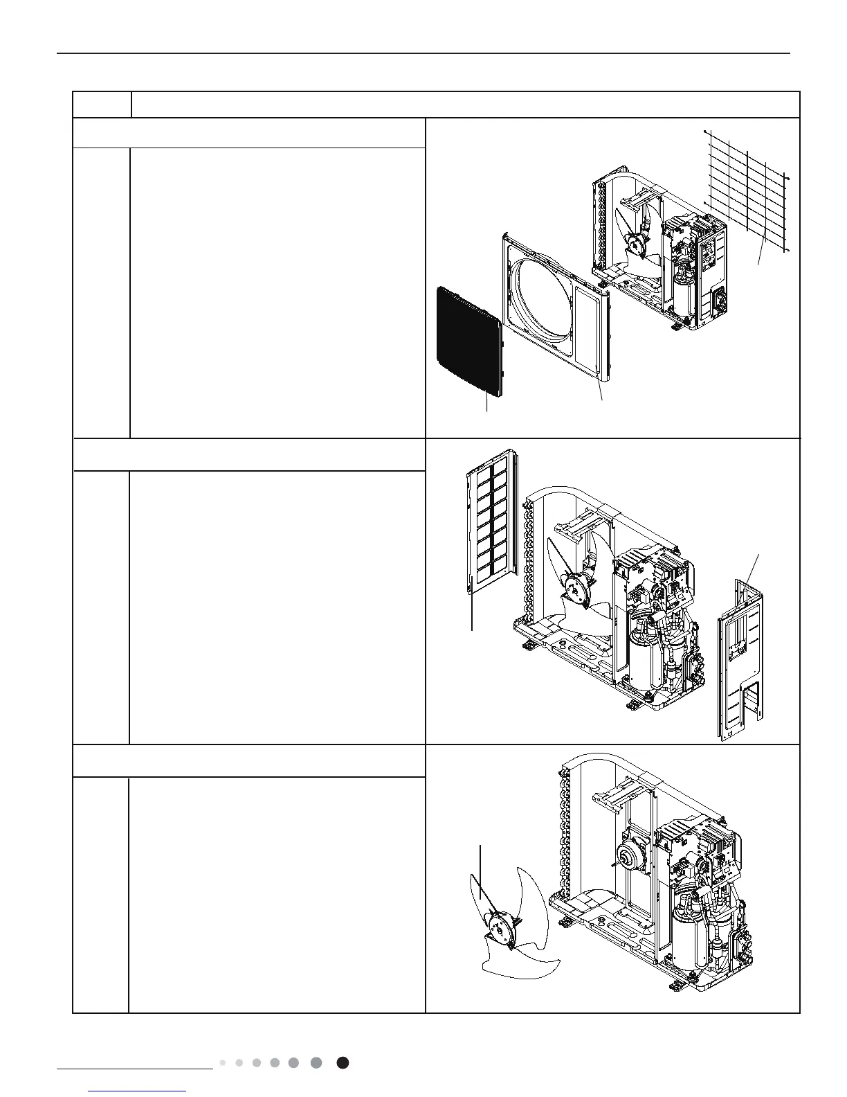
3.Remove grille 、protective grille and front panel
protective
grille
5.Remove axial flow blade
4.Remove right side plate、left side plate
Remove connection screws between the front grille
and the front panel. Then remove the front grille.
Remove connection screws connecting the front
panel with the chassis and the motor support, and
then remove the front panel.
Remove the screws fixing protective grille and then
remove the protective grille.
Remove the nut fixing the blade and then
remove the axial flow blade.
Remove the screws fixing right side plate、left side
plate and then remove them.
grille
panel
axial flow blade
right side plate
left side plate
ProcedureStep
 Loading...