Version 1.00 | Optidrive CoolVert User Guide | 15www.invertekdrives.com
3
Installation
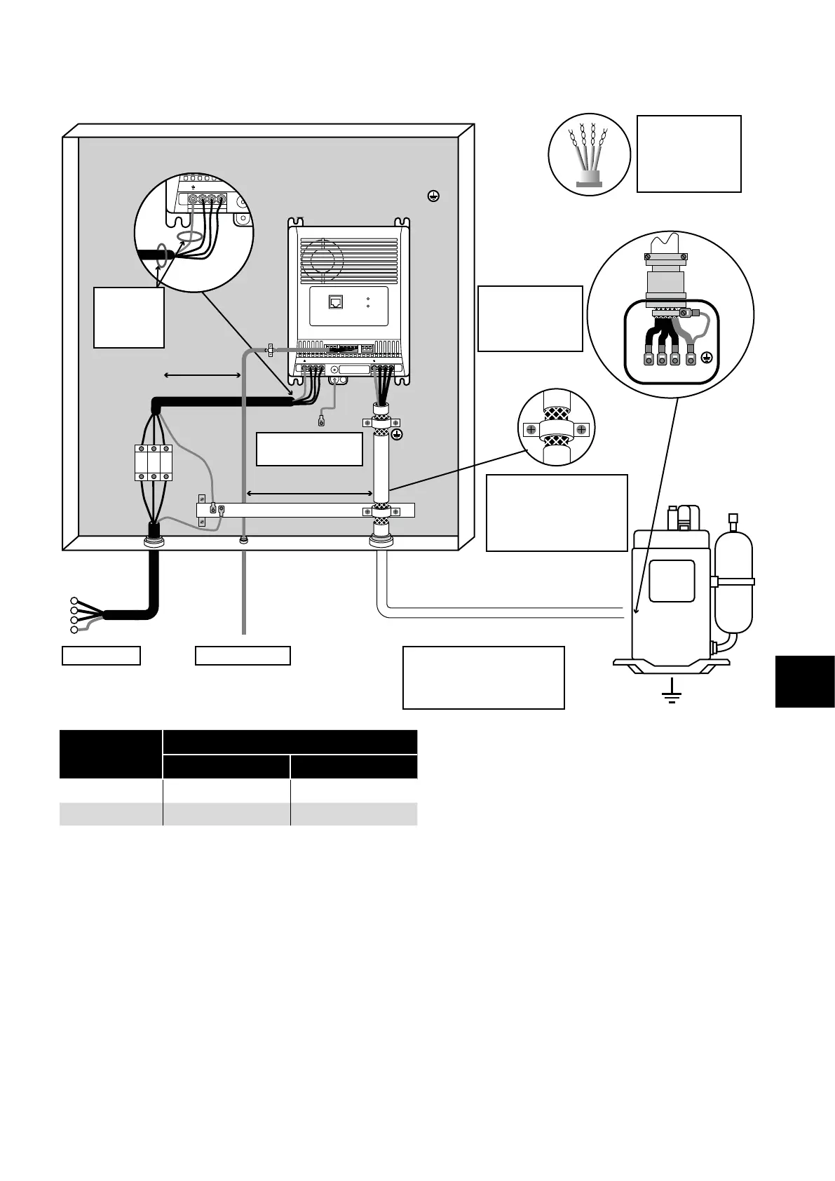
3.3.1. Recommended Installation for EMC Compliance
Control cables
Twisted-Pair shielded
cables for analog
control and motor
feedback signals.
Cable shield exposed
and 360° clamped to
grounded metal plate or PE
bar. All other 360° bonding
methods are acceptable.
Motor cable
3-phase and PE shielded cable.
Maintain shield as far as
possible along the cable
Control cablesMains - supply
Mounting plate
with conductive
service
≥ 100mm
≥ 100mm
Fuse /
MCB
L1
L2
L3
Ferrite rings
required for
single phase
variant only
Earth bonding drive
to backplate
1 2 3 4 5 6 7 8 9
10
11
STATUS 1
STATUS 2
L1 L2 L3 U V W
EMC
U
V
W PE
For Best-Practice use
360° bonding EMC
cable gland shielded
to motor chassis.
Voltage
Rating
Maximum permissible cable lengths
C1
1,2,4,5,6
C2
2,4,5,6
230V 1Phase 0 (1)
3
5 (10)
3
400V 3Phase 1 (5) 5 (10)
4
NOTE
Data in brackets shows permissible cable length with additional external EMC filter.
Details of optional external EMC filters listed in section 2.2.2. Optional External EMC Filters on page 6.