Version 1.00 | Optidrive CoolVert User Guide | 23www.invertekdrives.com
4
Set-up and Operation
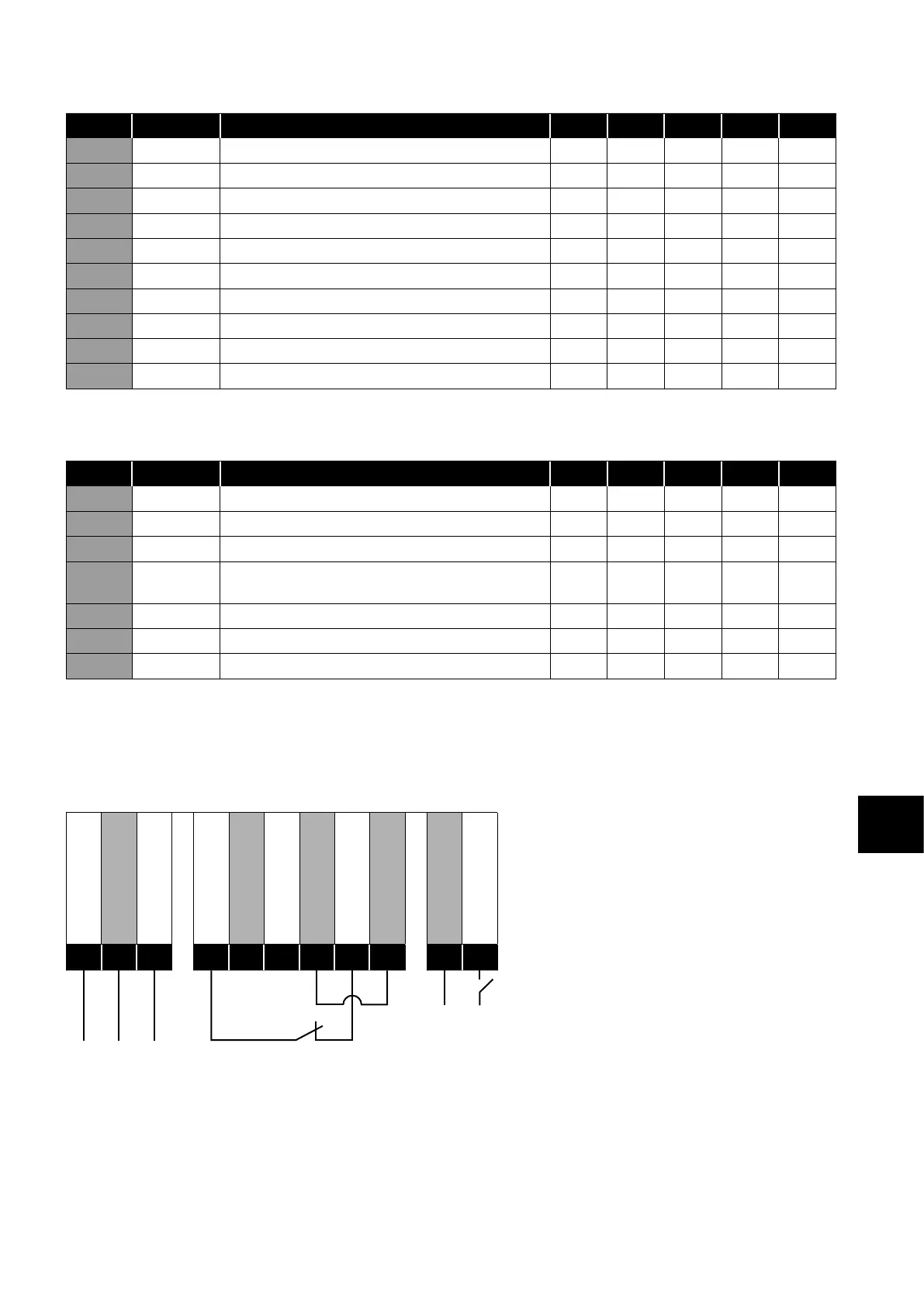
4.1.7. System Tuning
Par. Mod Add Description Def Min Max Unit R/W
5-03 503 Vector Speed Controller Proportional Gain 50 0 .1 400 % R/W
5-04 504 Vector Speed Controller Integral Time Constant 0.050 0.001 2.00 s R/W
7-01 701
Minimum Switching Frequency – Thermal Management
- - - kHz R/W
7-02 702 Auto-reset Delay 20 1 60 S R/W
7-03 703 Motor Stator Resistance (Rs) phase to phase W R/W
7-04 704 Motor Stator Inductance (Lsd) per phase mH R/W
7-05 705 Motor Stator Inductance (Lsq) per phase mH R/W
7-06 706 V/F Mode Magnetising Period - 0 5000 Ms R/W
7-07 707 Low Frequency Torque Boost Level 0.0 0.0 100 % R/W
7-08 708 Low Frequency Torque Boost, Frequency Limit 0.0 0.0 50 % R/W
The values for P7-03 through to P7-05 are gathered by the drive during the autotune process.
4.1.8. Thermal Protection
Par. Mod Add Description Def Min Max Unit R/W
5-07 507 Maximum Current Limit 110 20 150 % R/W
5-08 508 Motor Power Limit 13 0 0 13 0 % R/W
5-09 509 Motor Thermal Overload Management (Ixt) 0 0 1 - R/W
5-10 510 Drive Thermal Overload Management
(Drive Temperature Based)
0 0 1 - R/W
5-11 511 Motor Thermal Overload Retention Enable 1 0 1 - R/W
7-01 701
Minimum Switching Frequency – Thermal Management
- - - kHz R/W
7-02 702 Auto-reset Delay 20 1 60 S R/W
4.2. Modbus Connections
4.2.1 Minimum Control Wiring Required For Each Control Mode
See parameter 1-11 in section 4.1.6. Control Mode on page 22.
P1-11 = 0 - Modbus control
0V Common
Modbus TX/RX +
Modbus TX/RX -
+24V Output (100mA)
Digital Input 1
Analogue Input 1
0V Common
STO +
STO -
User Relay A
User Relay B
1
2
3
4
5
6
7
8
9
10
11
STO signal must be provided in order to permit running the motor. Start/Stop commands and speed reference are provided by serial
communication. In Modbus mode, the digital input and analogue input can be used as remote I/O by the controller, the relay output
can also be configured to be controlled by Modbus and used by the controller if required.