EasyManua.ls Logo

INVT CHV Series - User Manual

INVT CHV Series
138 pages
Print Icon
To Next Page IconTo Next Page
Loading...
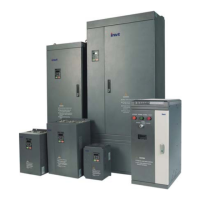
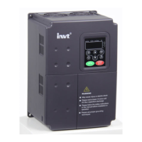
CHV Series Close loop Vector
Control Inverter
Operation Manual
z Thank you very much for your buying CHV series close loop vector control
inverter.
z Before use, please read this manual thoroughly to ensure proper usage. Keep
this manual at an easily accessible place so that can refer anytime as necessary.

Table of Contents

Questions and Answers

  • H
    hernandezelijahSep 6, 2025
    How to fix brake unit fault in INVT DC Drives?
    • T
      Tara CooperSep 7, 2025
      If your INVT DC Drives display 'Brake unit fault', it could be due to a braking circuit failure or a damaged brake tube. Inspect the braking unit and replace the braking tube if necessary. Another potential cause is too low resistance of the externally connected braking resistor; in that case, increase the braking resistance.
  • A
    Andrea GregoryAug 22, 2025
    What to do if there is over-current during acceleration in INVT DC Drives?
    • J
      jonesmeganAug 22, 2025
      To address over-current during acceleration with your INVT DC Drives, first, check for any short-circuits or ground faults at the inverter output. Inspect the motor for damage, worn insulation, or cable issues. If the hardware is fine, increase the Acc/Dec time or choose a higher capacity inverter. Also, review and adjust the V/F curve settings and check the load.
  • M
    Melissa CookSep 3, 2025
    How to troubleshoot communication fault in INVT DC Drives?
    • A
      Alyssa MaldonadoSep 4, 2025
      If the INVT DC Drives show a communication fault, it may be due to an improper baud rate setting. In this case, set the proper baud rate. It could also be due to receiving wrong data, so check communication devices and signals. Another potential cause is the communication being interrupted for a long time.
  • C
    Courtney GordonSep 2, 2025
    What causes output phase failure in INVT CHV DC Drives?
    • J
      Jennifer BondSep 2, 2025
      If the INVT DC Drives show an output phase failure, check the wiring and installation. This issue can arise from a broken wire in the output cable, a broken wire in the motor winding, or loose output terminals.
  • A
    arnoldjenniferSep 1, 2025
    What to do if DC bus under-voltage occurs in INVT CHV?
    • J
      josephjamesSep 1, 2025
      If the INVT DC Drives show a DC bus Under-voltage error, inspect the input power supply and wiring. This problem can arise from an open phase in the power supply, a momentary power loss, loose wiring terminals for the input power supply, or large voltage fluctuations in the power supply. Also inspect external equipment.
  • K
    Keith HoAug 30, 2025
    What causes input phase failure in INVT CHV?
    • T
      Taylor McbrideAug 30, 2025
      If your INVT DC Drives has input phase failure, check the wiring, installation, and power supply. The issue may stem from an open-phase in the power supply, a momentary power loss, loose wiring terminals for the input power supply, significant voltage fluctuations, or poor voltage balance between phases.
  • T
    Thomas WalkerAug 29, 2025
    What causes rectify overheat in INVT CHV DC Drives?
    • J
      Jacqueline CampbellAug 29, 2025
      If your INVT DC Drives display 'Rectify overheat', several factors could be responsible. The ambient temperature may be too high, or there could be a nearby heat source. Consider installing a cooling unit or removing the heat source. Check if the inverter's cooling fans have stopped or are damaged; if so, replace the cooling fan. Obstruction of the ventilation channel can also cause overheating; clear the channel. Lastly, a high carrier frequency can contribute to this issue; decrease the carrier frequency.
  • C
    Chris RoyAug 27, 2025
    How to troubleshoot IGBT Ph-U fault in INVT DC Drives?
    • L
      Lori WilsonAug 27, 2025
      If the INVT DC Drives show an IGBT Ph-U fault, it could be due to several reasons. The acceleration or deceleration time might be too short, so try increasing it. There might be a malfunction caused by interference, so inspect external equipment and eliminate any interference. Also, ensure that grounding is properly set up. If the issue persists, it could be an IGBT module fault, and you should ask for support.
  • M
    Michelle KaneAug 27, 2025
    What to do if there is a motor overload in INVT CHV DC Drives?
    • T
      Tammy BlairAug 27, 2025
      If the INVT DC Drives motor is experiencing an overload, consider these potential causes. The motor might be driving a heavy load at low speed for an extended period; if so, select a variable frequency motor. An improper V/F curve could also be the cause; check and adjust the V/F curve. Verify the motor’s overload protection threshold (PB.03) and adjust if necessary. Finally, check the load for any sudden changes.
  • A
    Amy RobertsAug 25, 2025
    Why does over-voltage occur during acceleration in INVT CHV DC Drives?
    • I
      icraneAug 26, 2025
      If your INVT DC Drives experience 'Over-voltage when acceleration', the deceleration time might be too short, causing excessive regenerative energy from the motor. Try increasing the deceleration time or connecting a braking resistor. Additionally, the input voltage may be too high; decrease it to stay within the specified limits.

Summary

Safety Precautions

Disassemble and Installation

Safety Instructions

Highlights critical safety instructions for handling and installing the inverter.

Wiring

Terminal Configuration

Details the main and control circuit terminal layouts for different models.

Typical Wiring Diagram

Presents a general wiring diagram for inverter connections.

Main Circuit Wiring

Explains how to wire the main power circuits of the inverter.

Control Circuit Wiring

Covers wiring precautions and details for control circuit terminals.

Operation

Operating Keypad Description

Explains the keypad layout, buttons, and indicator lights.

Operation Process

Details procedures for parameter setting, shortcut menu, fault reset, and autotuning.

Quick Start Guide

Provides a flowchart for a quick start-up procedure.

Detailed Function Description

P1 Group - Start and Stop Control

Explains parameters related to starting, stopping, braking, and acceleration/deceleration.

P2 Group - Motor Parameters

Details how to input and set motor-specific parameters for optimal performance.

P3 Group - Vector Control

Describes settings for vector control, including ASR and torque control parameters.

P4 Group - V;F Control

Covers V/F control settings, including curve selection and torque boost.

P5 Group - Input Terminals

Details the configuration and functions of various input terminals.

P9 Group - PID Control

Details the PID control setup, including preset, feedback sources, and tuning parameters.

PB Group - Protection Parameters

Covers various protection settings like phase failure, overload, and over-voltage protection.

Trouble Shooting

Fault and Trouble Shooting Guide

Lists fault codes, types, reasons, and solutions for common inverter issues.

Common Faults and Solutions

Provides solutions for common operational issues like no display or motor not moving.

Maintenance

INVT CHV Series Specifications

General IconGeneral
Output Frequency0~400Hz
Control ModeV/F control, Sensorless vector control (SVC), Torque control
Output Voltage0~Rated Input Voltage
Protection FeaturesOvercurrent, Overvoltage, Undervoltage, Overheating, Short circuit, Phase loss
Ambient Temperature-10°C ~ +40°C
Storage Temperature-20℃~+60℃
Humidity≤95% RH, non-condensing
Altitude≤1000m above sea level

Related product manuals