19
Type Terminal name
Function
description
Technical specifications
setted by dip switch.
4. Resolution: the minimum AI2/AI3 is
10mV/20mV when 10V corresponds to
50Hz.
GND
Analog reference
ground
Analog reference ground
AO1
Analog output
1. Output range:0~10V or 0~20mA
2. The voltage or the current output is
depended on the dip switch.
3. Deviation±1%,25°C when full range.
AO2
Relay output
RO1A Relay 1 NO contact
RO1 relay output, RO1A NO, RO1B NC,
RO1C common terminal
RO2 relay output, RO2A NO, RO2B NC,
RO2C common terminal
Contact capacity: 3A/AC250V
RO1B Relay 1 NC contact
RO2C
Relay 2 common
contact
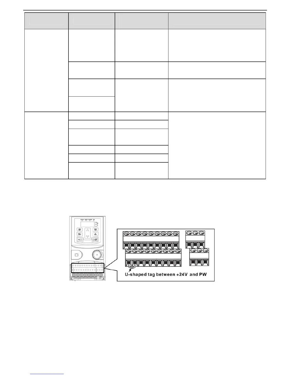
3.2.6 Input/Output signal connection figure
Please use U-shaped contact tag to set NPN mode or PNP mode and the internal or external power supply.
The default setting is NPN internal mode.
Figure 3-11 U-shaped contact tag
If the signal is from NPN transistor, please set the U-shaped contact tag between +24V and PW as below
according to the used power supply.
 Loading...