Goodrive300 Series VFD Peripherial options and parts
279
usage. You can select the brake system based on the actual operation conditions.
3. When using an external brake unit, set the brake voltage class of the brake unit properly by
referring to the manual of the dynamic brake unit. If the voltage class is set incorrectly, the VFD may
not run properly.
• Never use a brake resistor with a resistance below the minimum value
specified for the particular drive. The drive and the internal chopper are not
able to handle the overcurrent caused by the low resistance.
• Increase the power of the braking resistor properly in the frequent braking
situation (the frequency usage ratio is more than 10%).
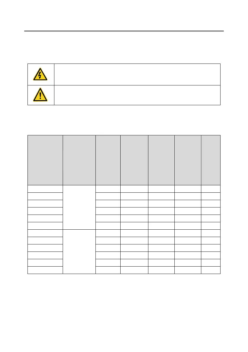
D.8.1.2 AC 3PH 380V(-10%)V–550V(+10%)
The VFDs of 500V (≤18.5kW) have embedded braking units but the VFDs of 500V (≥22kW) have
optional braking units. Please select the braking resistor according to actual operation (such as the
brake torque and brake usage requirements).
Brake
resistor
value
matched
with 100%
brake
torque (Ω)
Dissipation
power of
brake
resistor (kW)
(10% brake)
Dissipated
power of
brake
resistor
(kW)
(50%
brake)
Dissipated
power of
brake
resistor
(kW)
(80%
brake)
Min
allowed
brake
resistor
(Ω)
Note:
1. Select brake resistors according to the resistance and power data provided by our company.
2. The brake resistor may increase the brake torque of the VFD. The preceding table describes the
resistance and power for 100% brake torque, 10% brake usage, 50% brake usage, and 80% brake
usage. You can select the brake system based on the actual operation conditions.
 Loading...