Goodrive300 Series VFD Basic operation instruction
178
+
-
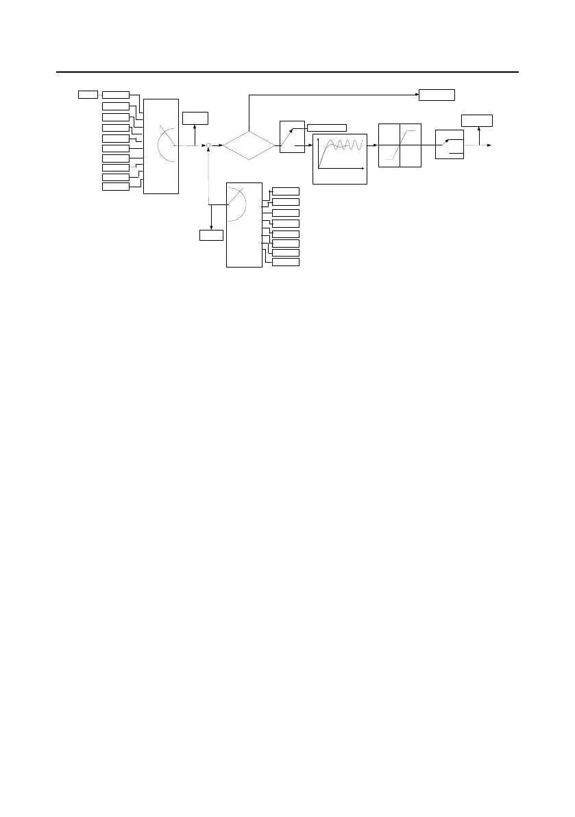
Given -feedback<P09.08?
P09.10
(lower limit of PID output)
P09.09
(the upper limit of PID
output )
0
1
P09.03
(the chrematistic of PID
output)
PID output
P17.00
P17.23
P09.08(PID control deviation limit)
P09.02
(PID feedback source selection)
P09.00
(PID given source selection)
P17.24
PID feedback
value
PID given value
Set frequency
0
1
2
3
4
5
6
7
8
9
Keypad
AI1
PROFIBUS
MODBUS
Multi-stage
speed
HDI
AI3
AI2
Ethernet
CAN
0
1
2
3
4
5
6
7
AI1
PROFIBUS
MODBUS
HDI
AI3
AI2
Ethernet
CAN
Y
N
PID stop
adjustment
Keypad setting PID given
Keep the current
frequency
Terminal function 25
PID control pause
Valid
Invalid
Kp P09.04(proportional gain)
Ti P09.05(integral time )
Td P09.06(differential time)
P09.01
Simple illustration of the PID control operation and adjustment:
Proportional adjustment (Kp): when there is an error between the feedback and the reference, a
proportional adjustment will be output. If the error is constant, the adjustment will be constant, too.
Proportional adjustment can respond to the feedback change quickly, but it cannot realize non-fault
control. The gain will increase with the adjustment speed, but too much gain may cause vibration. The
adjustment method is: set a long integral time and derivative time to 0 first. Secondly make the
system run by proportional adjustment and change the reference. And then watch the error of the
feedback signal and the reference. If the static error is available (for example, increasing the
reference, the feedback will be less than the reference after a stable system), continue to increase the
gain, vice versa. Repeat the action until the static error achieves a little value.
Integral time (Ti): the output adjustment will accumulate if there is an error between the feedback and
the reference. The adjustment will keep on increasing until the error disappears. If the error is existent
all the time, the integration adjustor can cancel the static error effectively. Vibration may occur as a
result of unstable system caused by repeated over-adjustment if the integration adjustor is too strong.
The features of this kind of vibration are: the fluctuating feedback signal (around the reference) and
increasing traverse range will cause vibration. Adjust the integral time parameter from a big value to a
little one to change the integral time and monitor the result until a stable system speed is available.
Derivative time (Td): when the error between the feedback and the reference, a proportional
adjustment will be output. The adjustment only depends on the direction and value of the error
change other than the error itself. The derivation adjustment controls the change of feedback signals
according to the changing trend when it fluctuates. Because the derivation may enlarge the
interference to the system, especially the frequent-changing interference, please use it carefully.
When P00.06, P00. 07=7 or P04.27=6, the running mode of the VFD is procedure PID control.
7.15.1 General steps of PID parameters setting:
a Ensure the gain P
When ensure the gain P, firstly cancel the PID integration and derivation (set Ti=0 and Td=0, see the
 Loading...