Goodrive300 Series VFD Communication protocol
217
T1-T2-T3-T4 (transmission time of 3.5 bytes)
The RTU response command is:
T1-T2-T3-T4 (transmission time of 3.5 bytes)
6EH
T1-T2-T3-T4 (transmission time of 3.5 bytes)
10.4.5 The definition of data address
The address definition of the communication data in this part is to control the running of the VFD and
get the state information and related function parameters of the VFD.
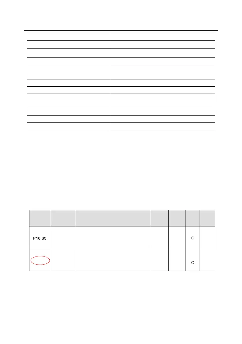
10.4.5.1 Function code address representation rules
The parameter address occupies 2 bytes with the fact that the high bit is in the front and the low bit is
in the behind. The range of high and low byte are: high byte—00–ffH; low byte—00–ffH. The high byte
is the group number before the radix point of the function code and the low byte is the number after
the radix point. But both the high byte and the low byte should be changed into hex. For example
P05.06, the group number before the radix point of the function code is 05, then the high bit of the
parameter is 05, the number after the radix point 06, then the low bit of the parameter is 06, then t he
function code address is 0506H and the parameter address of P10.01 is 0A01H.
Name
Function
code
Description
Setting
range
Default
value
Modify
Serial
No.
P10.01
Simple
PLC
Simple
PLC
memory
0: Stop after running once
1: Run at the final value after running once
2: Cycle running
0: Power loss without memory
1: Power loss with memory
0–2
0–1
0
0
354.
355.
Note: P29 group is the factory parameter which cannot be read or changed. Some parameters cannot
be changed when the VFD is in the running state and some parameters cannot be changed in any
state. The setting range, unit and related instructions should be paid attention to when modifying the
function code parameters.
Besides, EEPROM is stocked frequently, which may shorten the usage time of EEPROM. For users,
 Loading...