Goodrive170-PV Series Solar Pump Inverter Installation guidelines
-11-
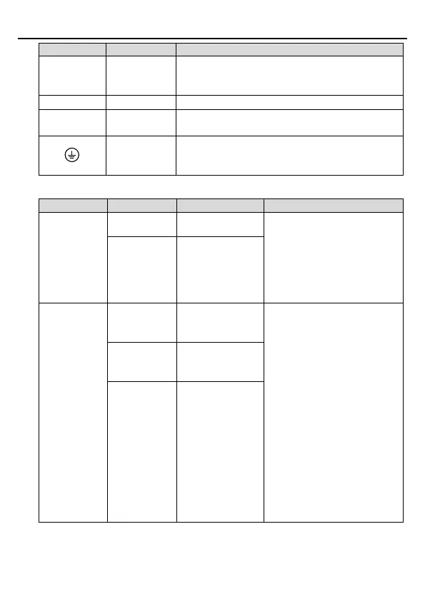
3PH (1PH) AC input terminals, connected to the grid
Note: Use the screws equipped with the inverter for
wiring.
Input terminals of photovoltaic panels.
3PH AC output terminals, connected to the pump
motor in most cases.
Safety
protection
grounding
Grounding terminal for safe protection; each machine
must be properly grounded.
3.2.2 Control circuit terminals
Used to externally provide
24V±10% power supply. Max.
output current: 200mA
Generally used as the the
working power supply of digital
input/output or the external
sensor power supply
Forcibly switches to
power frequency
Terminal feature parameters:
1. Internal impedance: 3.3kΩ
2. 12–24V voltage input is
acceptable
3. Max. input frequency: 1kHz
S1: Forcibly switches to power
frequency (Switching-on
indicates switching to power
frequency, and switching-off
indicates input controlled by the
keypad.)
S2: It connects to the high water
level switch of NO contact by
default.
S3: It connects to the low water
level switch of NC contact by
default.

 Loading...


