Goodrive170-PV Series Solar Pump Inverter Options
-57-
Appendix A Options
A.1 Boost module
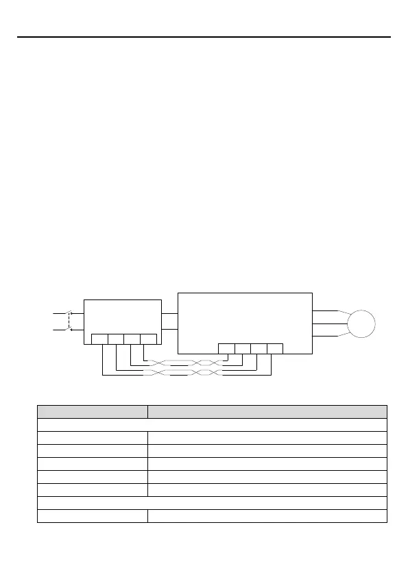
The pump inverters of 2.2kW support an optional boost module (PP100-3R2-PV) to
improve the utilization ratio of the PV cell module. The figure below shows the wiring
method.
1. Connect PV+ and PV- of the boost module to positive and negative input terminals
of the PV cell module respectively.
2. Connect output terminals (+) and (-) of the boost module to input terminals (+) and (-)
of the pump inverter respectively.
3. Connect 422-communication receiving terminal RX of the boost module to
422-communication sending terminal TX of the pump inverter, connect
422-communication sending terminal TX of the boost module to 422-communication
receiving terminal RX of the pump inverter, and use two sets of twisted pairs for
wiring.
4. Ensure that the wiring is connected properly, and switch on the breaker Q1 at the
DC side for automotive running.
Figure A-1 Connection between the boost module and the inverter
GD170-PV
inverter
(+)
(-)
U
V
W
PV
input
Q1
PP100-3R2-PV
Boost module
(+)
(-)
PV+
PV-
Water
pump
Shielded twisted pairs
422RX+
422TX-
422RX-
422TX+
422RX+
422RX-
422TX+ 422TX-
Boost module specifications:

 Loading...


