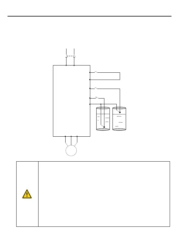
The DC breaker Q1 must be installed as the protection switch for PV
input.
In parallel connection, the combination box special for PV must be
used.
When the distance between the PV cell module and inverter exceeds
10 meters, Type-II surge protection devices must be configured at the
DC side.
When the distance between the pump and inverter exceeds 50
meters, it is recommended to configure output reactors. See appendix
A.4 for the output reactor model selection.
The inverter automatically runs after being powered on. If parameters
need to be set, follow the parameter setting instructions in Chapter 5.
 Loading...


