-14-
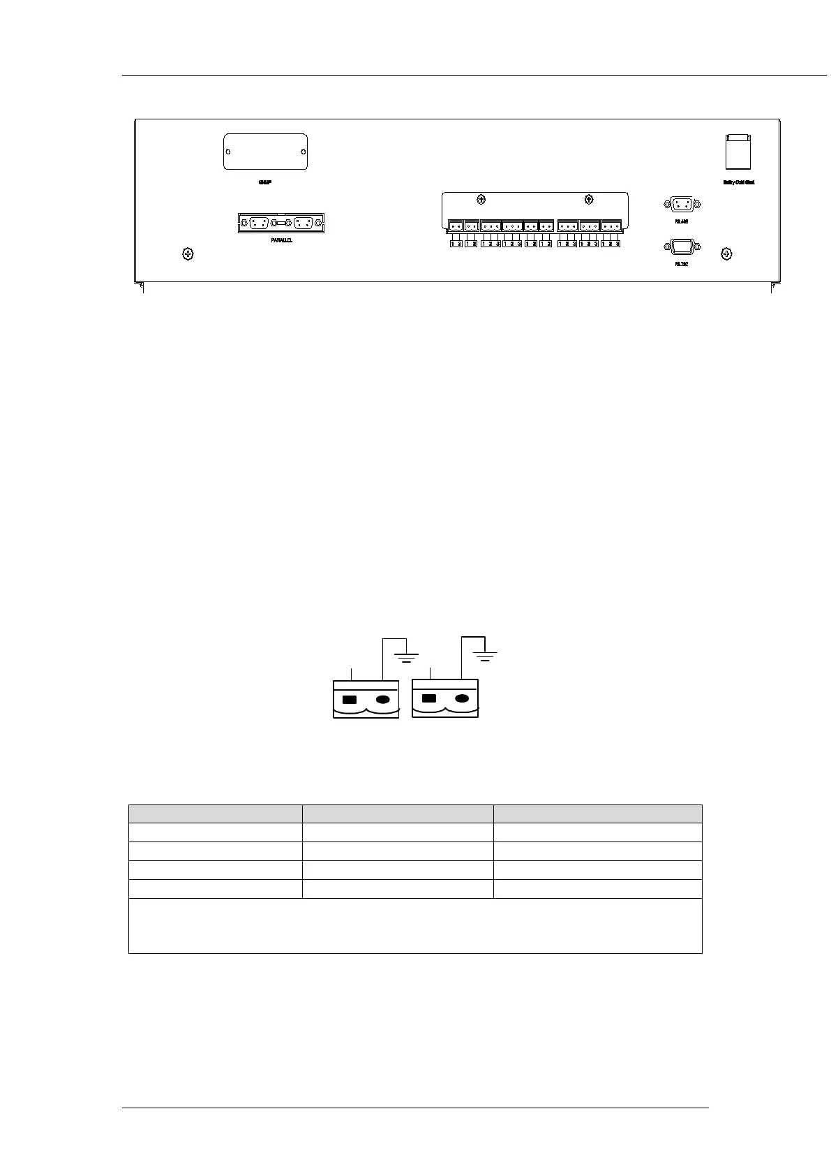
Fig 2-6 Dry contact interface and communication interface
The UPS accepts external signal from zero-voltage (dry) contacts connected through external dry
contact terminals produced and phoenix terminals that are in bypass module. Through software
programming, these signals become active when these contacts connect to +24V to ground.The cables
connected to DRY terminal must be separated from power cables. Moreover, these cables should be
double insulated with a typical 0.5 to 1.5 mm
2
2.6.1 Dry Contact Interface of Battery and Environmental Temperature Detection
(Optional)
cross-section area for a maximum connection length
between 25 and 50 meters.
The input dry contact J2 and J3 can detect the temperature of batteries and environment
respectively, which can be used in environment monitoring and battery temperature compensation 1.
J2 and J3 interfaces diagram are shown in fig 2-7, the description of interface is in table 2-2.
Fig 2-7 Diagram of J2 and J3 dry contact for temperature detecting
Table 2-2 Description of input dry contact interface J2 and J3
Battery temperature detection
Environment temperature detection
Note:
Specified temperature sensor is required for temperature detection (R25=5Ohm, B25/50=3275),
please confirm with the manufacturer, or contact local maintenance engineers when placing an order.
2.6.2 Remote EPO Input Port (Optional)
The UPS has an Emergency Power OFF (EPO) function. This function can be activated by pressing
a button on the control panel of the UPS or through a remote contact provided by the user. The EPO
pushbutton is protected by a hinged plastic cover.