-26-
Chapter 4 Installation of Parallel
Operation System
The parallel operation system is installed as required by the installation procedures of the single
system and this chapter.
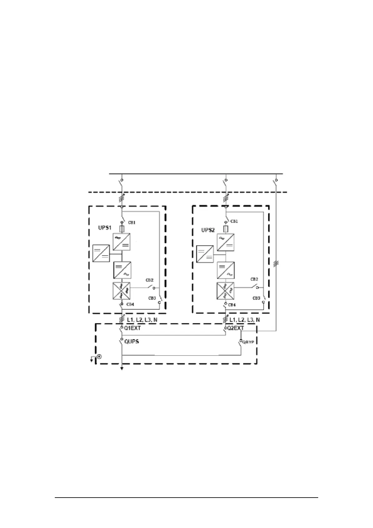
The single devices are put parallel and connected as shown in fig. 4-1, and the difference between
the lengths of the output cables of the single devices is not more than 10m. It is recommended to use an
external bypass cabinet to facilitate maintenance and system testing.
Fig. 4-1 Typical 1+N parallel operation system
Note: when the load exceeds is the capacity of the single device, the maintenance bypass
switch CB3 must be removed.
The cables for the parallel operation provide double insulation shielding up to 30m long, the control
cables for the parallel operation must be connected with all single devices to form a closed loop, as
shown in fig.4-2.
L1, L2, L3, N terminal
L1, L2, L3, N terminal