-16-
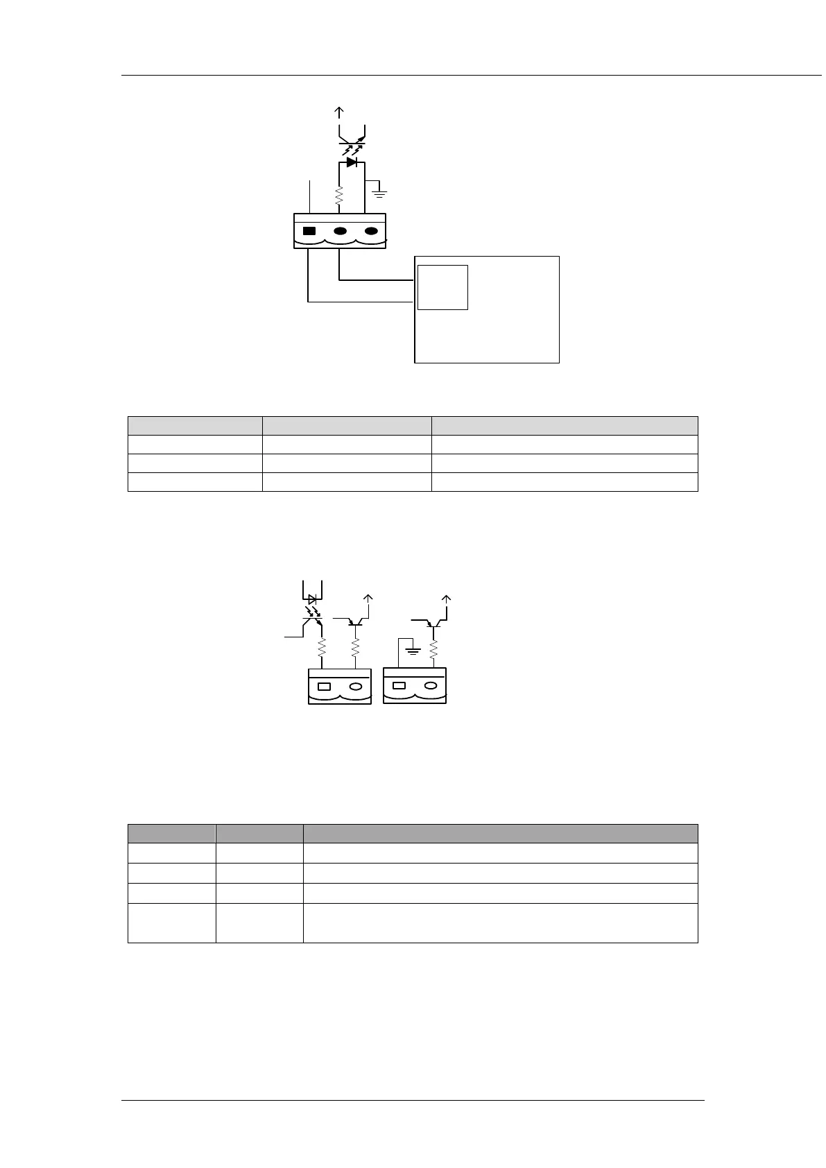
J5
G
E
N
+24V
AUX-N.O.
AUX-N.O.
发电机
Fig 2-9 Diagram of status interface and connection of generator
Table 2-4 Description of maintenance bypass switch and output switch status interface
Connection status of generator
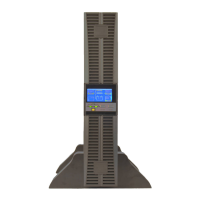
2.6.4 BCB Interface (Optional)
J6 and J7 are battery circuit breaker (BCB) interface. The interface diagram is shown in fig 2-10 and
interface description is shown in table 2-5.
B
C
B
_
D
R
V
B
C
B
_
C
O
N
T
J6
J7
B
C
B
_
O
N
L
+24V
+24V
+24V
Fig 2-10 BCB Interface
Table 2-5 Description of BCB Interface
J6.1 BCB_DRV BCB drive signal: providing +24V, 20mA drive signal
J6.2 BCB_CONT BCB contact status
,
connect to BCB
’
s normal open signal
J7.1 GND Power ground
J7.2 BCB_ONL
BCB online input
(
normal open
),
it shows BCB is online when this
signal connects to GND.
2.6.5 Battery Warning Output Dry Contact Interface (Optional)
J8 is the output dry contact interface, which outputs the battery warnings of low or excessive voltage,
when the battery voltage is lower than set value, an auxiliary dry contact signal will be provided via the
isolation of a relay. The interface diagram is shown in fig 2-11, and description is shown in table 2-6.