IONPURE
®
VNX CEDI Modules
Page 18 IP-MAN-VNX-1019-EN.pdf
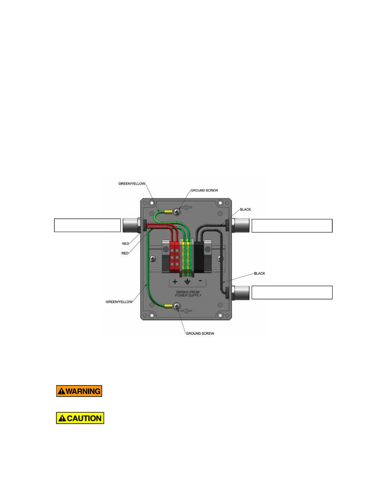
3.3. Electrical Connections
All VNX modules have an on-board electrical junction box to allow convenient connection
of the module to the DC power supply that provides the driving force for the
electrodeionization process. Only one electrical connection is required per module.
Power connections to the terminal strip inside the module junction box (see Figure 3-5)
should be made with 12 or 10 AWG (4.0 or 6.0 mm
2
) wire and conduit connections should
be supplied via the 7/8” (22 mm) junction box through-hole. Wire stripping length is 0.35”
(9 mm) and terminal strips screws should be tightened to 1.6 N-m (14 lb
f
-in).
The DC wire color conventions used on the VNX modules are as follows:
· Red (+) to DC positive terminal of power controller
· Black (–) to DC negative terminal of power controller
· Green/Yellow to earth ground
Figure 3-5 Inside the VNX Junction Box (2-stack module)
3.3.1. Electrical Precautions
· Disconnect power before opening any enclosure and follow
accepted Lockout/Tagout procedures when working on the
system.
· Do not run AC and DC wiring within the same conduit. This may
cause interference and lead to malfunctions.
◄ Return from stack
◄ Return from stack
◄ Out to stacks
 Loading...