¶µ : Selection button to select the desired virtual floppy disk (00-
99 if previously preset)
When the virtual floppy changes from one to another, dots light up
next to the digits. Please wait before you use the disk drive until the
dots disappear.
• Caution: When LED 1 – Busy – lights up, do not under any
circumstances remove the USB Stick or deploy the selection
button, or else you might incur data losses.
• The virtual floppy images must be in correct sequence in order
to be selected with the selection button.
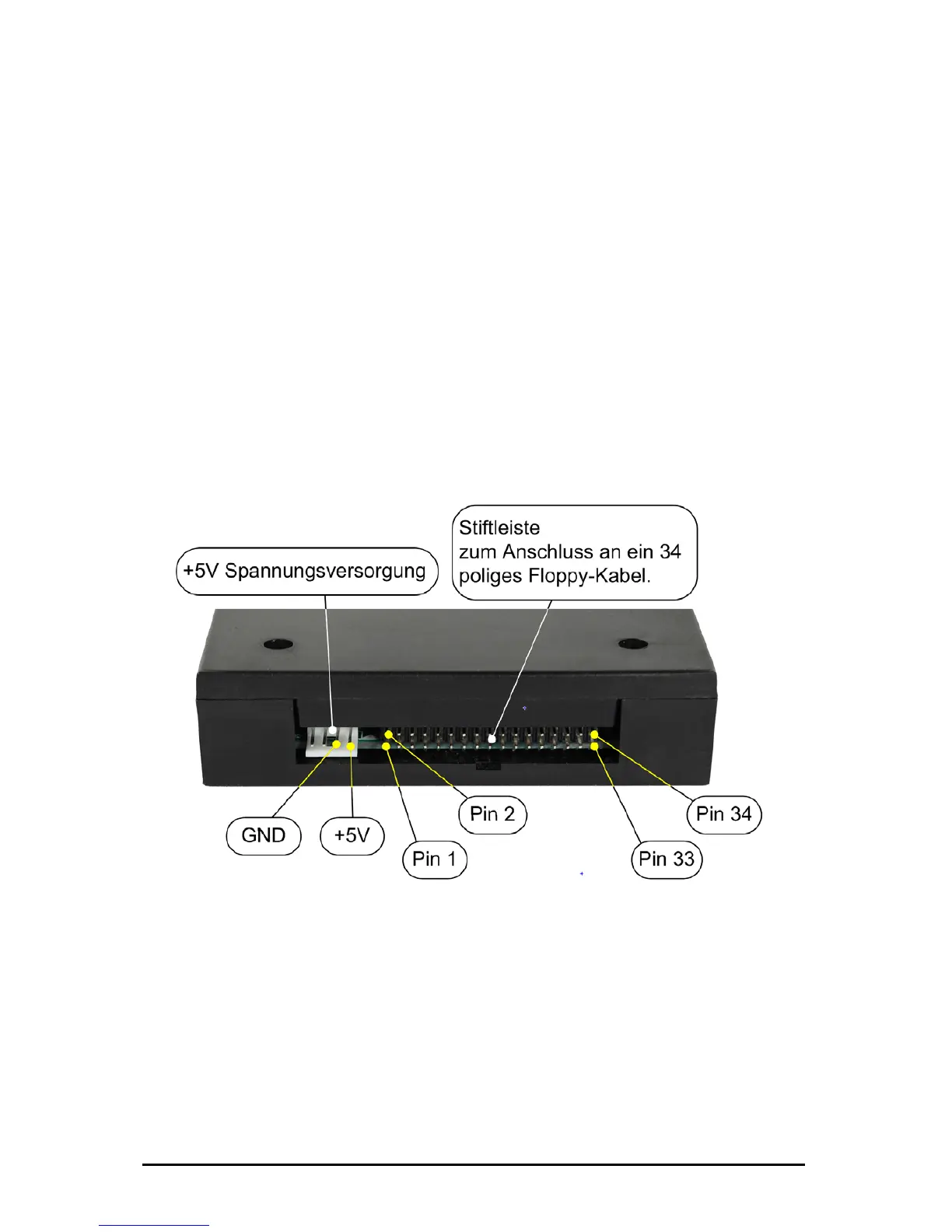
5. Back – description, connections
At the back of the disk drive you will find the connection for the
voltage supply (+5V DC) and the 34-pin interface to connect the
floppy disk drive controller.
Please check for correct polarity of voltage supply when connecting
the floppy disk drive. GND (ground) is usually indicated by a black
wire, and +5V by red wire.
Please also correctly attach the 34-pin connection cable.
Subject to change without prior notice Date: 09-03-10
ipcas GmbH USB Floppy Disk Emulator – USB Floppy v0.2 Page 6 of 17