c. Drill a 7/16” hole and tap a 1/4” NPT port to a locaon
downstream from the lter and upstream from any
chemical introducon points. Install a tubing connector
(included) and ex tubing to be connected to the le
side ow cell port containing the ow switch. The in-line
lter will also be installed in this line and mounted to a
horizontal pipe with band clamps (included). Note: Verify
that the lter is installed with direconal arrows poinng
in the direcon of the ow.
d. Drill a 7/16” hole and tap a 1/4” NPT port to a locaon that
is subject to vacuum or reduced pressure. Install a tubing
connector (included) and ex tubing to be connected to
the right side ow cell port. Note: We recommend that
this tubing connector be installed into the drain hole on
the sucon side of the pump for best performance.
e. Cut a 3” - 6” length of ex tubing and insert into the ow
cell’s sample stream port (center).
3. pH and ORP Sensors
Note: Carefully unpack the pH and ORP sensors and set aside in a
clear area unl ready to install into the ow cell.
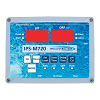
a. Verify that the M720 controller power is OFF.
b. Carefully remove the plasc protecve caps from the
sensors and store in a separate locaon for future re-use.
c. Slide the glass end of each sensor (pH and ORP) into their
corresponding compression ngs located at the top of
the ow cell. Ensure that the p is submerged into the
water to within 1/2” from the boom of the ow cell.
Hand ghten each nut ng.
12
M720 pH/ORP Controller Owner’s Manual