37
Set Flow Sensor Model
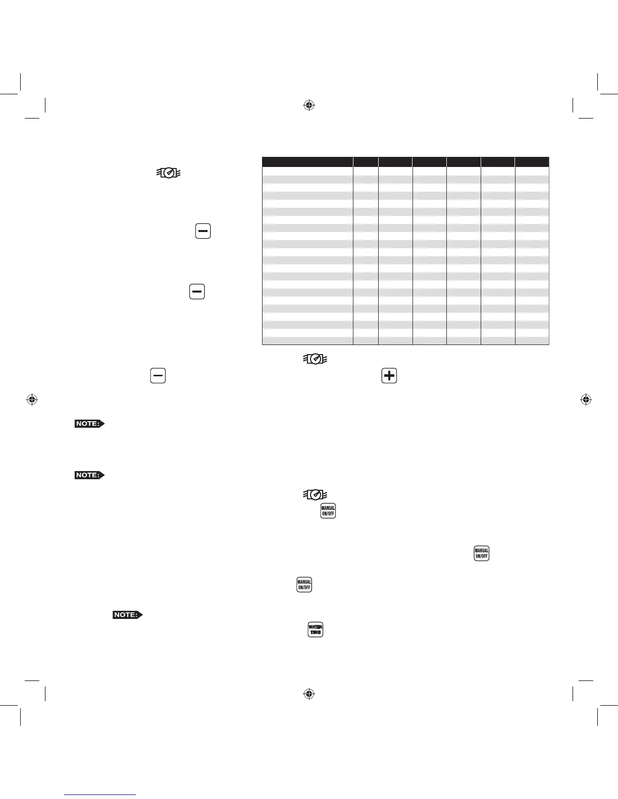
Flow Sensor Data Table
Step 1 – Place the Function dial to the FLOW
SENSING position. Enable
ow sensing if its disabled.
Step 2 – While in the K Value/Sensor Size
screen, select the ow sensor size
code by pressing the button.
Use the Flow Sensor table below to
nd your specic size code.
Example: If using Sensor Model
TFS-075, press the button until
the S value in the display equals 75
(S=75).
Set Flow Unit
Step 1 – Place the Function dial to the FLOW SENSING position. Enable ow sensing if its disabled.
Step 2 – Press the button to change the ow unit to the presets. Press the button repeatedly until the desired
ow unit is displayed (GPM = Gallons per Minute, CFM = Cubic Feet per Minute, CMH = Cubic Meter per
Hour, LPM = Liter per Minute or PPS = Pulses per Second).
If the sensor you choose is not represented on the chart, use “Unknown Flow Sensor” size code “00”. The ow
unit for “Unknown Flow Sensor” can only be set to PPS.
Read/Learn Station Flow Value
MC-E will only read/learn the ow of stations with active runtimes.
Step 1 – Place the Function dial to the FLOW SENSING position. Enable ow sensing if its disabled.
Step 2 – Verify that all ow parameters are set, then press the button to read/learn each of the station’s actual
ow. It will read/learn the station’s ow value until the ow delay time expires. The default ow delay is one
minute. During “Learn Flow” each station will be displayed with the ow that the sensor is measuring.
To learn the ow value of a specic station, enter the two digit station number and press the button.
To learn the ow value of a group of stations, enter the two digit station number of the 1st station, the two digit
station number of the last station and press the button. The MC-E will sequentially read the ow value for
each station in the group.
Press any key to stop the learning process. Learned values will not be saved when stopped.
Step 6 – To review each station ow parameters, press the button. MC-E will sequentially display each of the
station’s ow parameters.
Catastrophic Flow Sensor Protection (Optional Setup)
The MC-E provides a function to detect an unscheduled ow. Any detected ow in the system when no station is watering is
considered an unscheduled ow. The MC-E has the capability to monitor any unscheduled ow and activate Station 1 as a ow
alarm to shut off a normally open master valve.
The ow alarm can be used to activate a normally open master valve which is installed ahead of the other valves on the system.
Station 1 must be set to ow alarm in SETUP for this to function. The F00 (“F00” represents the upper ow limit for the main
line) parameters in the ow setup will dictate the overow threshold of the main line. When at any time MC-E detects an
unscheduled ow that violates F00 overow parameters, MC-E will activate station 1 to close the normally open master valve.
Install Critical Flow Shut off Master Valve
Step 1 – Find a location along the sub-main pipe that services
the irrigation system to install the normally open
master valve. The location should be ahead of any
valves in the irrigation system. Refer to the valves
installation instructions for further details.
Step 2 – Route a two-wire irrigation cable from the valve to
the controller. Connect one solenoid wire to the valve
common terminal and the remaining solenoid wire to
the Station 1 terminal.
Step 3 – Check for proper operation.
Configure Station 1 for Flow Alarm Function
Step 1 – Place the Function dial to the SETUP
position.
Step 2 – Press . Station 1 setup screen will be displayed.
Step 3 – Press the button to congure Station 1 as ow alarm to activate a normally-open master valve or press the
button to congure it back to station. Press to activate your selection.
Step 4 – Return the Function dial to AUTO/RUN position.
Catastrophic Flow Parameters
IMPORTANT! Set catastrophic ow, “F00”, above the highest owing valve in the system.
The setting for “F00” is the master valve, and therefore the main line, upper ow limit. If this limit is not set higher than the ow for
the largest station, any station with a ow greater than the main line ow limit will set off the ow alarm and shut down the system.
Step 1 – To set F00’s catastrophic ow limit, place the Function dial to the FLOW SENSING position. Navigate
to the Over percentage limit screen by pressing the button. If “F00” is not the displayed station number,
press the button repeatedly until “F00” is selected.
Step 2 – Enter a catastrophic ow limit that is above the learned ow of the station with the highest ow in the system
and press .
The ow sensor should be “sized” correctly so the catastrophic ow limit for the system is still within
the sensor’s reading range.
Step 3 – Adjust the catastrophic Overow. See “Set Overow percentages” section.
Flow Sensor Model K Value Offset GPM L/Sec
Size
Code
Pipe
Size
Unkown Flow Sensor 00 Unkown 10PPSPPS
TFS-050 50 1/2’’ 0.07800 0.9 1.2 – 12 0.1 – 0.8
TFS-075 75 3/4’’ 0.15630 0.9 2.7 – 28 0.2 – 1.8
TFS-100 1001’’ 0.26112 1.2 5.0 – 50 0.3 – 3.2
TFS-150 or 228PV15xx-xxxx 150 1.5’ 1.69900 -0.3160 5 – 100 0.3 – 6.3
TFS-200 or 228PV20xx-xxxx 200 2.0’’ 2.84290 0.14350 10 – 200 0.6 – 12.6
TFS-300 or 228PV30xx-xxxx 300 3.0’’ 8.30900 0.22700 20 – 300 1.3 – 18.9
TFS-400 or 228PV40xx-xxxx 400 4.0’’ 13.74283 0.23707 40 – 500 2.5 – 31.5
250BR0700x-xxxx73/4’’ 0.43680 0.56800
250BR1000x-xxxx101’’ 0.39740 0.26180
0.25 Liters Per Pulse 11 0.25 L/P1 0
0.50 Liters Per Pulse 12 0.50 L/P1 0
1 Liter Per Pulse 13 1 L/P1 0
2.5 Liters Per Pulse 14 2.5 L/P1 0
5 Liters Per Pulse 15 5 L/P1 0
10 Liters Per Pulse 16 10 L/P1 0
25 Liters Per Pulse 17 25 L/P1 0
50 Liters Per Pulse 18 50 L/P1 0
100 Liters Per Pulse 19 100 L/P1 0
250 Liters Per Pulse 20 250 L/P1 0
500 Liters Per Pulse 21 500 L/P1 0
1000 Liters Per Pulse 22 1000 L/P1 0
 Loading...