2
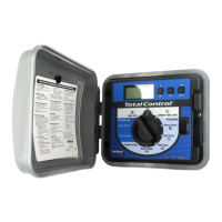
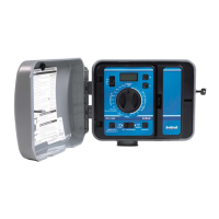
Figure 1
1 LCD Display: For viewing time, program and status information.
2 + /On & – /Off Buttons: For entry of program information.
3 Next Button: For selection of information to be programmed or reviewed.
4
Function Dial: For selecting the programming and operating functions.
5
Current Time & Date: For setting the current time and date.
6 Latch Knobs: Quick-release latches for hinged TM control panel.
7 Station Times: For setting individual watering time for each station.
8 Program Select Switch: For selection of programs A, B, C or D.
9
Start Times: For setting the time each program cycle will start.
10 Water days: For setting a watering day schedule for each program.
11
% Water Budget: For the increase or decrease of station times for all stations within
a program without changing program memory (Season and/or Monthly Adjust). To
the set number of programs (1–4) which can operate simultaneously. Remote Radio
Communication is also enabled or disabled in this function.
12 Sensor Control Switch: To override rain switch sensor input.
13 Program Erase: For erasing information within a selected program.
14 Manual Program Cycle: For manual operation start of a selected program watering
cycle.
15 Manual Single Station: For timed or untimed operation of a single station.
16 Off / Rain Delay: For immediate shut down of all controller output. Programmable
output delay for 1–7 days (Rain Delay).
17 Run: For automatic operation.
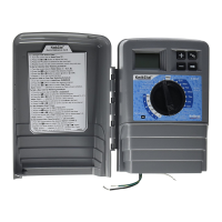
Figure 2
18 Remote Port: Connection port for optional remote control receiver.
19 Spare Fuse Holder: Holds a 2.0A slow-blow spare fuse.
20 Valve Common Terminals: For the connection of up to four fi eld (24V) common
wires.
21
Valve Wire Terminals: For the connection of valve control wires.
22
Earth Ground Lugs: For connection of a 6 AWG (10 mm2) copper ground wire(s).
23 Terminal Strip: For the connection of 120 or 230–240 V a.c. power wiring.
24 Master Valve Terminal: For the connection of a master valve or pump start relay
control wire.
25 Sensor Connection Terminals: For the connection an optional normally-closed rain
switch device.
26 Hot Post: 24 V a.c. output for valve zone identifi cation.
27 Battery Compartment: 9-volt alkaline battery access compartment.
28 Safety Fuse: Replaceable 2.0A slow-blow fuse provides protection from an internal
short-circuit condition.
29 Climate Logic Weather System, CMR-Kit and R-100-Kit interface connection.
30 Top mounting hole.
31 Lower mounting hole.
CONTROLLER COMPONENTS