DOC. MIE91093 Rev. 1.34 Page 102 of 145
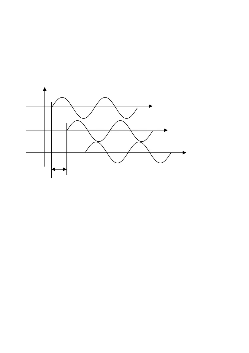
As test starts, all voltages are modified from VN to Vf; the
three fault current should be injected at the same time. This is
not completely true with the three T1000 PLUS because of the
zero crossing feature: the three phases have zero crossings
that are time shifted by 6.66 ms. The following figure explains
the situation; this means that in first zone the trip time will be
increased by 13,3 ms.
1) Fault current
The current will be adjusted on all the faulty phases; its
value is the one selected by the operator (for instance, 10 A).
2) Healthy voltages phase angles
Choose the test angle in the R-X plane. If the distance relay is
set on the CT star point towards Busbar, the angle Φ(I-V) has
the same value but negative, otherwise it has the same value.
These angles are adjusted prior to actual zone testing, as
follows.
Start the test; adjust the fault current; adjust the fault voltage
at 30 V. Now select on all T1000 PLUS the auxiliary Vac phase
with respect to the current, as follows:
AUX VAC/DC > Aux Vac control > Phase > Reference:
current ESC
This adjustment will not be modified during tests.