DOC. MIE91093 Rev. 1.34 Page 49 of 145
1.6.2. Connection to voltage output
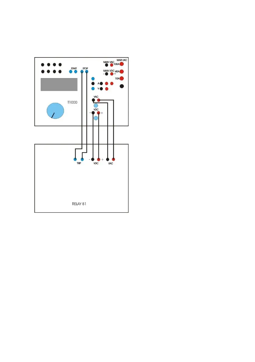
The following is the connection schematic,
. Power-on T1000 PLUS, acting on switch (2): the internal light
turns on.
. Press the button (70) to have the AC voltage available.
. If you wish to use the DC voltage output to supply the relay
under test, press the button (69), then use knob (20) to
adjust the voltage value, that is displayed on the LCD display
(23). Connect the DC supply input of the relay to sockets (63).
. Select the auxiliary voltage range and the pre-fault + fault
mode as follows.
AUX VAC/VDC > Aux VAC control > Range (RET)
Mode > Pre-fault+fault > Pre-
fault amplitude > (Value) ESC