DOC. MIE91093 Rev. 1.34 Page 113 of 145
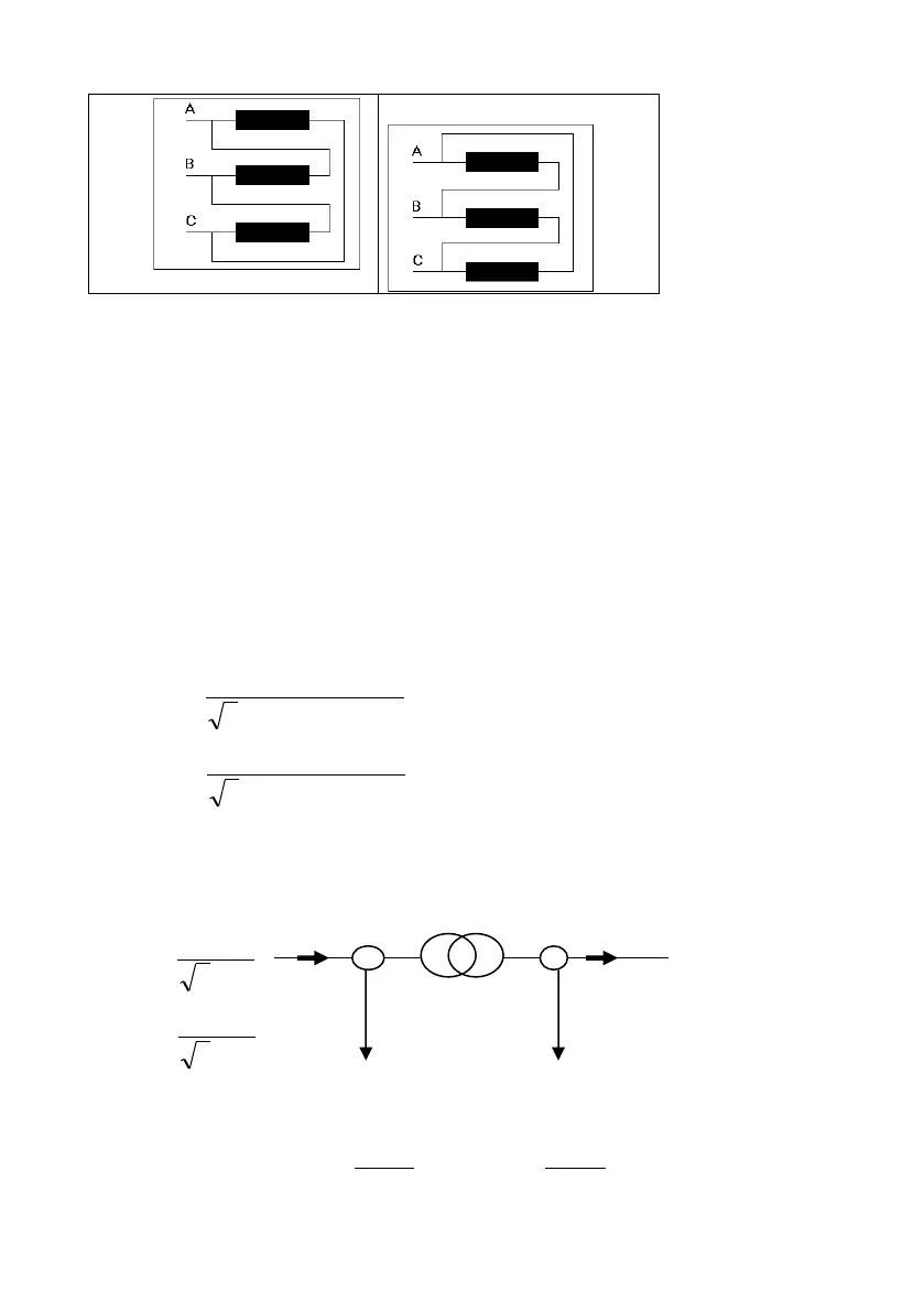
A perfect test would require the use of 6 output
currents; however, as T1000 PLUS + D1000 can
generate only two currents, and only in phase, only a
single phase test can be performed.
The setting of the differential relay is computed by computing
the transformer taps, that are the Ipu (per unit current) after
the CT on both HV and LV sides, when the transformer is at
full load. The transformer TAPs are calculated according to:
the nominal power Pn, the primary and secondary voltage V
1n
and V
2n
, the CTRatio, and the nominal current In:
These values are the p.u. nominal current at relay level after
the CT. They are fundamental when calculating the test
currents to apply to the relay.