DOC. MIE91093 Rev. 1.34 Page 116 of 145
relay, while we apply the differential current only to one side.
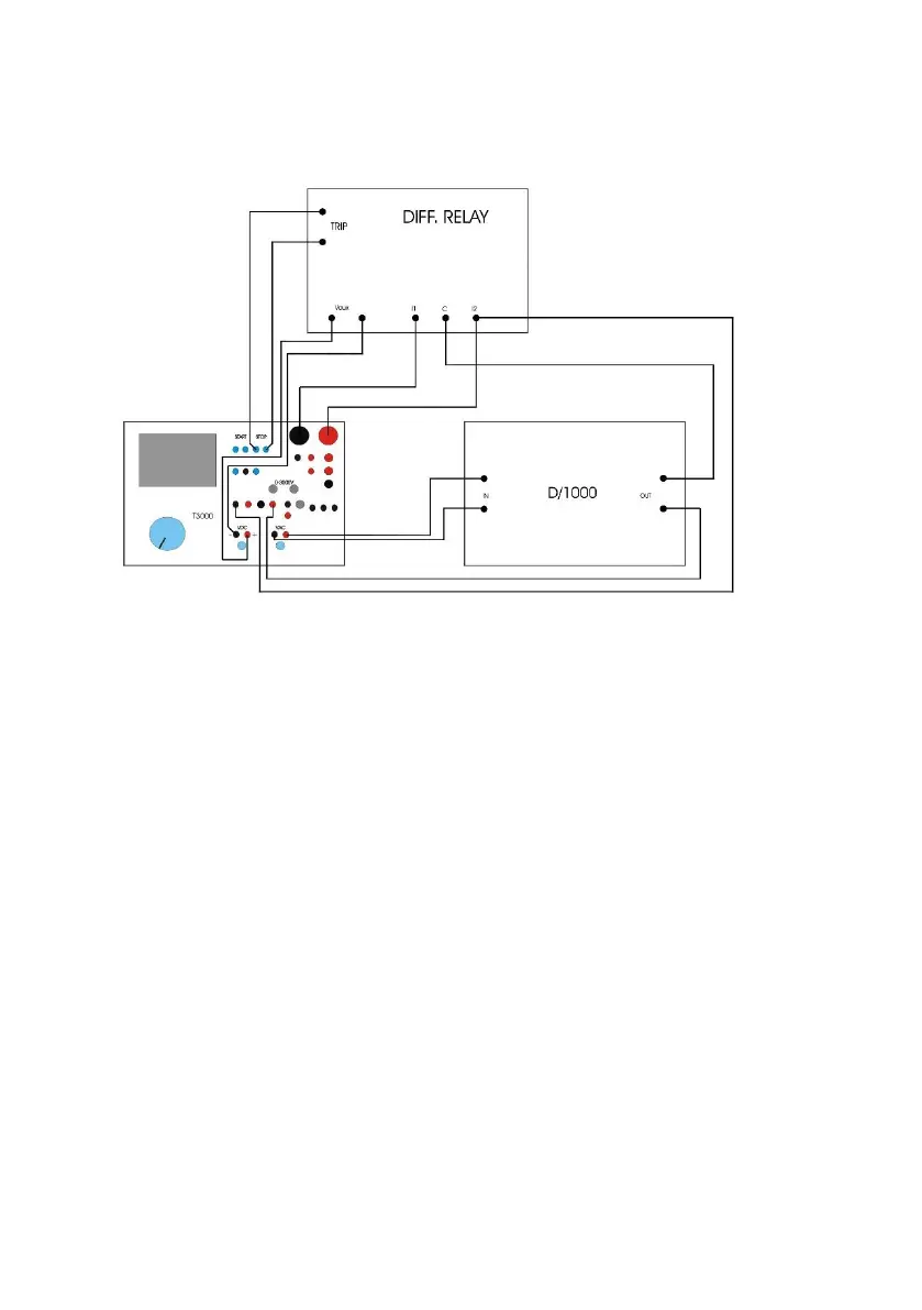
The connection scheme is the following.
The following is the D1000 front panel. There are two pairs of
sockets: IN and OUT. IN is to be connected to the VCAUX
output of T1000 PLUS; D1000 converts the voltage into
current, and generates the differential current, that is
measured prior to connection to the relay. So, when we say
that the differential current is to be adjusted, this means
adjusting the auxiliary voltage.